Chapter 7 Servo Parameters
7-24
Revision June 2010
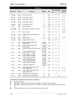
This parameter is used to determine that the speed and torque limit functions are
enabled or disabled. If P1-02 is set to 11, it indicates that the speed and torque
limit functions are enabled always. The users can also use DI signals, SPDLM and
TRQLM to enable the speed and torque limit functions. Please note that DI signals,
SPD0, SPD1, TCM0, and TCM1 are used to select the command source of the speed
and torque limit.
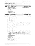
P1 - 03
AOUT
Pulse Output Polarity Setting
Address: 0106H, 0107H
Default: 0
Related Section:
Applicable Control Mode: ALL
Section 3.3.3
Unit: N/A
Range: 0 ~ 13
Data Size: 16-bit
Display Format: Hexadecimal
Settings:
A: Analog monitor outputs polarity
0: MON1(+), MON2(+)
1: MON1(+), MON2(-)
2: MON1(-), MON2(+)
3: MON1(-), MON2(-)
B: Position pulse outputs polarity
0: Forward output
1: Reverse output
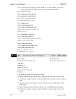
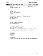
P1 - 04
MON1
Analog Monitor Output Proportion 1
(CH1)
Address: 0108H, 0109H
Default: 100
Related Section: Section 6.4.4
Applicable Control Mode: ALL
Unit: % (full scale)
Range: 0 ~ 100
Data Size: 16-bit
Display Format: Decimal
Summary of Contents for ASD-B2-0121-B
Page 1: ......
Page 13: ...Table of Contents xii Revision June 2010 This page intentionally left blank...
Page 17: ...Chapter 1 Unpacking Check and Model Explanation 1 4 Revision June 2010 ECMA Series Servo Motor...
Page 87: ...Chapter 4 Display and Operation 4 12 Revision June 2010 This page intentionally left blank...
Page 131: ...Chapter 6 Control Modes of Operation 6 22 Revision June 2010 Time Domain...
Page 267: ...Chapter 8 MODBUS Communications 8 18 Revision June 2010 This page intentionally left blank...
Page 271: ...Chapter 9 Maintenance and Inspection 9 4 Revision June 2010 This page intentionally left blank...
Page 291: ...Chapter 11 Specifications 11 8 Revision June 2010 11 3 Servo Motor Speed Torque Curves...


