Chapter 7 Servo Parameters
Revision June 2010
7-93
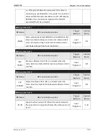
i.e. DO signal OLW will be activated). If the drive is
continuously overloaded for 8 seconds, the overload
alarm will be detected and shown on the LED display
(AL006). Then, Servo Fault signal will be ON (DO
signal ALRM will be activated).
Setting value: 0x11
DO Name
DO Function Description
Trigger
Method
Control
Mode
WARN
Servo warning activated. WARN is activated when the
drive has detected Reverse limit error. Forward limit
error, Emergency stop, Serial communication error,
and Undervoltage these fault conditions.
Level
Triggered
All
Setting value: 0x13
DO Name
DO Function Description
Trigger
Method
Control
Mode
SNL
(SCWL)
Reverse software limit. SNL is activated when the
servo drive has detected that reverse software limit is
reached.
Level
Triggered
All
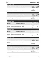
Setting value: 0x14
DO Name
DO Function Description
Trigger
Method
Control
Mode
SPL
(SCCWL)
Forward software limit. SPL is activated when the
servo drive has detected that forward software limit is
reached.
Level
Triggered
All
Setting value: 0x19
DO Name
DO Function Description
Trigger
Method
Control
Mode
SP_OK
Speed reached output. SP_OK will be activated when
the speed error is equal and below the setting value of
P1-47.
Level
Triggered
S, Sz
Summary of Contents for ASD-B2-0121-B
Page 1: ......
Page 13: ...Table of Contents xii Revision June 2010 This page intentionally left blank...
Page 17: ...Chapter 1 Unpacking Check and Model Explanation 1 4 Revision June 2010 ECMA Series Servo Motor...
Page 87: ...Chapter 4 Display and Operation 4 12 Revision June 2010 This page intentionally left blank...
Page 131: ...Chapter 6 Control Modes of Operation 6 22 Revision June 2010 Time Domain...
Page 267: ...Chapter 8 MODBUS Communications 8 18 Revision June 2010 This page intentionally left blank...
Page 271: ...Chapter 9 Maintenance and Inspection 9 4 Revision June 2010 This page intentionally left blank...
Page 291: ...Chapter 11 Specifications 11 8 Revision June 2010 11 3 Servo Motor Speed Torque Curves...


