


Revision June 2010
7-1
Chapter 7 Servo Parameters
7.1
Definition
There are following five groups for drive parameters:
Group 0: Monitor parameters
(example: P0-xx)
Group 1: Basic parameters
(example: P1-xx)
Group 2: Extension parameters
(example: P2-xx)
Group 3: Communication parameters
(example: P3-xx)
Group 4: Diagnosis parameters
(example: P4-xx)
Abbreviation of control modes:
PT: Position control mode (command from external signal)
S : Speed
control
mode
T
:
Torque control mode
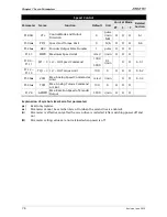
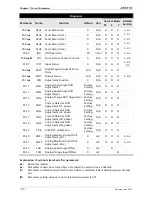
Explanation of symbols (marked after parameter)
(
★
)
Read-only register, such as P0-00, P0-01, P4-00.
(
▲
)
Parameter cannot be set when Servo On (when the servo drive is enabled), such as P1-00,
P1-46 and P2-33.
(
z
)
Parameter is effective only after the servo drive is restarted (after switching power off
and on), such as P1-01 and P3-00.
(
)
Parameter setting values are not retained when power is off, such as P2-31 and P3-06.
Summary of Contents for ASD-B2-0121-B
Page 1: ......
Page 13: ...Table of Contents xii Revision June 2010 This page intentionally left blank...
Page 17: ...Chapter 1 Unpacking Check and Model Explanation 1 4 Revision June 2010 ECMA Series Servo Motor...
Page 87: ...Chapter 4 Display and Operation 4 12 Revision June 2010 This page intentionally left blank...
Page 131: ...Chapter 6 Control Modes of Operation 6 22 Revision June 2010 Time Domain...
Page 267: ...Chapter 8 MODBUS Communications 8 18 Revision June 2010 This page intentionally left blank...
Page 271: ...Chapter 9 Maintenance and Inspection 9 4 Revision June 2010 This page intentionally left blank...
Page 291: ...Chapter 11 Specifications 11 8 Revision June 2010 11 3 Servo Motor Speed Torque Curves...