Chapter 7 Servo Parameters
Revision June 2010
7-15
pulse number in pulse.
When reading the drive status through Modbus communication, the system should
read two 16-bit data stored in the addresses of 0012H and 0013H to form a 32-bit
data.
(0013H : 0012H) = (high byte : low byte)
When reading the drive ststus through the keypad, if P0-02 is set to 23, VAR-1 will
quickly show for about two seconds and then the value of P0-09 will display on the
display.
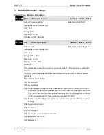
P0 - 10
★
CM2
Status Monitor 2
Address: 0014H, 0015H
Default: N/A
Related Section:
Applicable Control Mode: ALL
Section 4.3.5
Unit: N/A
Range: N/A
Data Size: 32-bit
Display Format: Decimal
Settings:
This parameter is used to provide the value of one of the status monitoring
functions found in P0-02. The value of P0-10 is determined by P0-18 (desired drive
status) through communication setting or the keypad. The drive status can be read
from the communication address of this parameter via communication port.
When reading the drive status through the keypad, if P0-02 is set to 24, VAR-2 will
quickly show for about two seconds and then the value of P0-10 will display on the
display.
P0 -11
★
CM3
Status Monitor 3
Address: 0016H, 0017H
Default: N/A
Related Section:
Applicable Control Mode: ALL
Section 4.3.5
Unit: N/A
Range: N/A
Data Size: 32-bit
Display Format: Decimal
Settings:
This parameter is used to provide the value of one of the status monitoring
functions found in P0-02. The value of P0-11 is determined by P0-19 (desired drive
status) through communication setting or the keypad. The drive status can be read
from the communication address of this parameter via communication port.
When reading the drive status through the keypad, if P0-02 is set to 25, VAR-3 will
quickly show for about two seconds and then the value of P0-11 will display on the
display.
Summary of Contents for ASD-B2-0121-B
Page 1: ......
Page 13: ...Table of Contents xii Revision June 2010 This page intentionally left blank...
Page 17: ...Chapter 1 Unpacking Check and Model Explanation 1 4 Revision June 2010 ECMA Series Servo Motor...
Page 87: ...Chapter 4 Display and Operation 4 12 Revision June 2010 This page intentionally left blank...
Page 131: ...Chapter 6 Control Modes of Operation 6 22 Revision June 2010 Time Domain...
Page 267: ...Chapter 8 MODBUS Communications 8 18 Revision June 2010 This page intentionally left blank...
Page 271: ...Chapter 9 Maintenance and Inspection 9 4 Revision June 2010 This page intentionally left blank...
Page 291: ...Chapter 11 Specifications 11 8 Revision June 2010 11 3 Servo Motor Speed Torque Curves...


