Chapter 6 Control Modes of Operation
6-4
Revision June 2010
The source of pulse command can also be determined by digital input, PTCMS. When the
digital input function is used, the source of pulse command is from digital input.
Position pulse can be input from these terminals, PULSE (41), /PULSE (43), HPULSE (38),
/HPULSE (36), SIGN (37), /SIGN (39) and HSIGN (42), /HSIGN (40). It can be an open-collector
circuit or line driver circuit. For the detail wiring, please refer to 3.6.1.
6.2.2 Structure of Position Control Mode
Basic Structure:
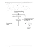
In order to pursue the goal of perfection in position control, the pulse signal should be
modified through position command processing and the structure is shown as the figure
below:
Using parameter P1-01 can select P mode. Electronic gear ratio can be set in P modes to
set proper position revolution. ASDA-B2 series servo drive also provides low-pass filter,
which are used whenever the motor and load need to be operated more smoothly. As for
the information of electronic gear ratio, and low-pass filter, please refer to the following
sections 6.2.3 and 6.2.4.
Summary of Contents for ASD-B2-0121-B
Page 1: ......
Page 13: ...Table of Contents xii Revision June 2010 This page intentionally left blank...
Page 17: ...Chapter 1 Unpacking Check and Model Explanation 1 4 Revision June 2010 ECMA Series Servo Motor...
Page 87: ...Chapter 4 Display and Operation 4 12 Revision June 2010 This page intentionally left blank...
Page 131: ...Chapter 6 Control Modes of Operation 6 22 Revision June 2010 Time Domain...
Page 267: ...Chapter 8 MODBUS Communications 8 18 Revision June 2010 This page intentionally left blank...
Page 271: ...Chapter 9 Maintenance and Inspection 9 4 Revision June 2010 This page intentionally left blank...
Page 291: ...Chapter 11 Specifications 11 8 Revision June 2010 11 3 Servo Motor Speed Torque Curves...


