Chapter 5 Trial Run and Tuning Procedure
Revision June 2010
5-15
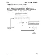
5.5.4 Semi-Auto Mode Tuning Flowchart
Set P2-32 to 2 (2: Semi-Auto Mode [Non-continuous adjustment] )
The servo drive will continuously perform the adjustment for a period of time. After the
system inertia becomes stable, it will stop estimating the system inertia, save the
measured load inertia value automatically, and memorized in P1-37. When switching from
other modes, such as Manual Mode or Auto Mode, to Semi-Auto Mode, the servo drive will
perform continuous adjustment for estimating the load inertia (P1-37) again. The servo
drive will refer to the frequency response settings of P2-31 when estimating the system
inertia.
P2-31 : Auto Mode Stiffness Setting (Default setting: 80)
In Auto mode and Semi-Auto mode, the speed loop frequency response settings are as
follows:
1 ~ 50Hz : Low stiffness and low frequency response
51 ~ 250Hz : Medium stiffness and medium frequency response
251 ~ 550Hz : High stiffness and high frequency response
Adjust P2-31: Increase the setting value of P2-31 to enhance the frequency response or
reduce the noise.Continuously perform the adjustment until the satisfactory performance
is achieved.
Summary of Contents for ASD-B2-0121-B
Page 1: ......
Page 13: ...Table of Contents xii Revision June 2010 This page intentionally left blank...
Page 17: ...Chapter 1 Unpacking Check and Model Explanation 1 4 Revision June 2010 ECMA Series Servo Motor...
Page 87: ...Chapter 4 Display and Operation 4 12 Revision June 2010 This page intentionally left blank...
Page 131: ...Chapter 6 Control Modes of Operation 6 22 Revision June 2010 Time Domain...
Page 267: ...Chapter 8 MODBUS Communications 8 18 Revision June 2010 This page intentionally left blank...
Page 271: ...Chapter 9 Maintenance and Inspection 9 4 Revision June 2010 This page intentionally left blank...
Page 291: ...Chapter 11 Specifications 11 8 Revision June 2010 11 3 Servo Motor Speed Torque Curves...


