Chapter 3 Connections and Wiring
3-34
Revision June 2010
3.5 Serial Communication Connector CN3
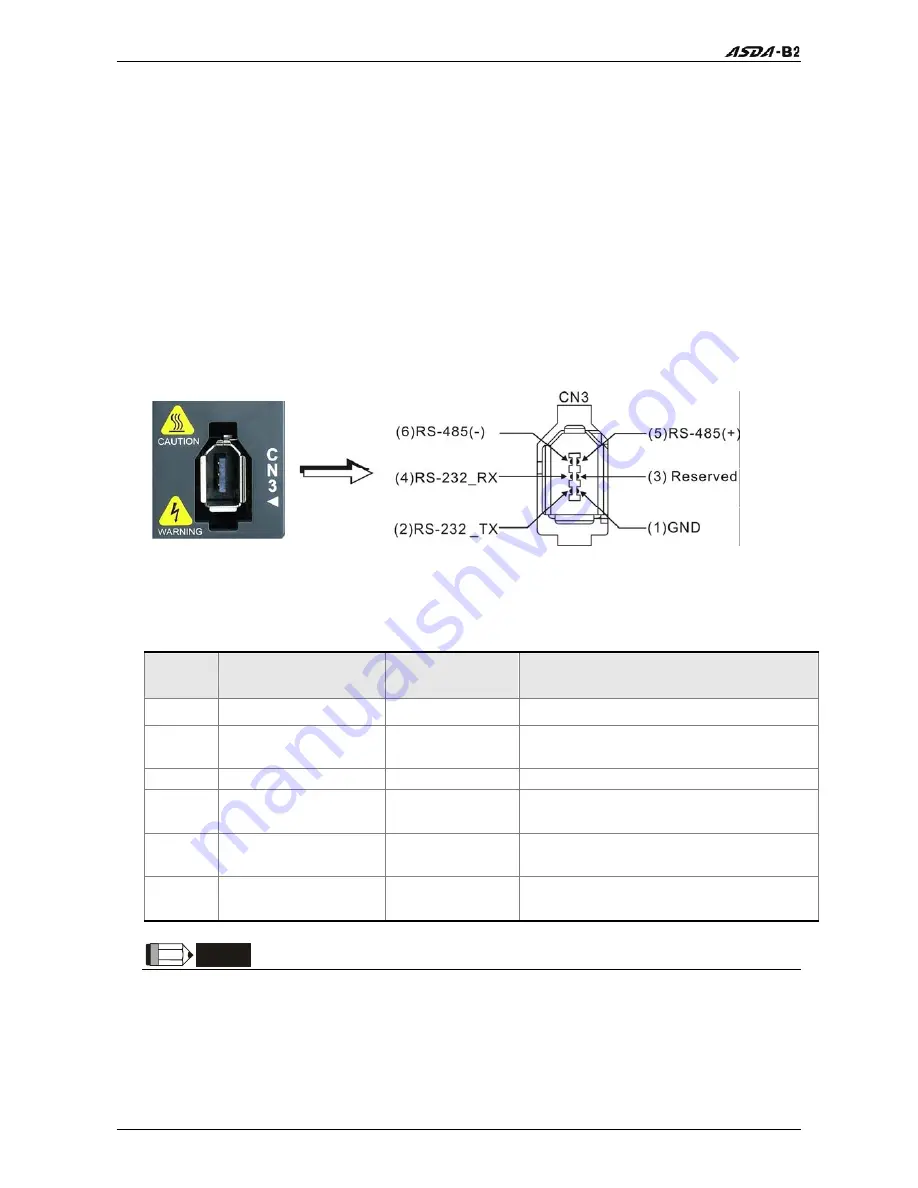
3.5.1 CN3 Terminal Layout and Identification
The servo drive can be connected to a PC or controller via a serial communication
connector. Users can operate the servo drive through PC software supplied by Delta
(contact to the dealer). The communication connector/port of Delta servo drive can
provide three common serial communication interfaces: RS-232, RS-485, and RS-422
connection. RS-232 is mostly be used but is somewhat limited. The maximum cable
length for an RS-232 connection is 15 meters (50 feet). Using RS-485 or RS-422 interface
can allow longer distance for transmission and support multiple drives to be connected
simultaneously.
CN3 Drive Connector
CN3 Terminal Signal Identification
PIN No.
Signal Name
Terminal
Identification
Description
1 Grounding
GND
Ground
2
RS-232 data
transmission
RS-232-TX
For data transmission of the servo drive.
Connected to the RS-232 interface of PC.
3 -
-
Reserved
4
RS-232 data receiving
RS-232_RX
For data receiving of the servo drive.
Connected to the RS-232 interface of PC.
5
RS-485 data
transmission
RS-485(+)
For data transmission of the servo drive
(differential line end)
6
RS-485 data
transmission
RS-485(-)
For data transmission of the servo drive
(differential line driver - end)
NOTE
1) For the connection of RS-485, please refer to page 8.3.
2) There are two kinds of IEEE1394 communication cables available on the market. If the user
uses one kind of cable, which its GND terminal (Pin 1) and its shielding is short-circuited,
the communication may be damaged. Never connect the case of the terminal to the ground
of this kind of communication cable.
Summary of Contents for ASD-B2-0121-B
Page 1: ......
Page 13: ...Table of Contents xii Revision June 2010 This page intentionally left blank...
Page 17: ...Chapter 1 Unpacking Check and Model Explanation 1 4 Revision June 2010 ECMA Series Servo Motor...
Page 87: ...Chapter 4 Display and Operation 4 12 Revision June 2010 This page intentionally left blank...
Page 131: ...Chapter 6 Control Modes of Operation 6 22 Revision June 2010 Time Domain...
Page 267: ...Chapter 8 MODBUS Communications 8 18 Revision June 2010 This page intentionally left blank...
Page 271: ...Chapter 9 Maintenance and Inspection 9 4 Revision June 2010 This page intentionally left blank...
Page 291: ...Chapter 11 Specifications 11 8 Revision June 2010 11 3 Servo Motor Speed Torque Curves...


