


4. Operating Instruction
4.2 Advanced operation guide
157
4.2.15.2 Measurement Example
This section mainly describes how to carry out harmonic distortion measurements of signals.
Step 1. Set signal source as below:
Set frequency on signal source to 1.960GHz.
Set signal amplitude to -10dBm.
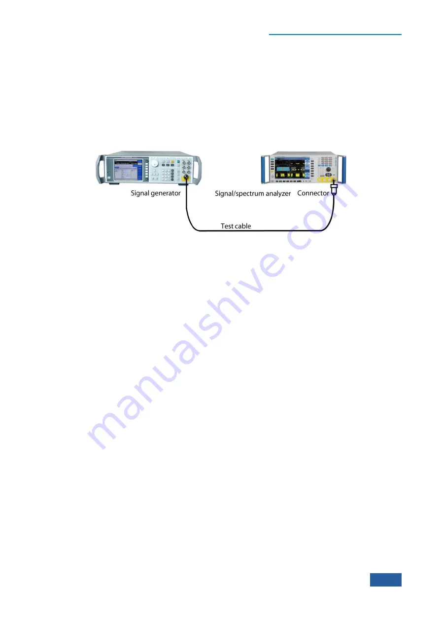
Step 2. Connect the radio frequency output port of the signal source to that of the analyzer. As shown in
Fig. 4.76:
Fig. 4.76 Connection Settings of Harmonic Distortion Measurements
Step 3. set the analyzer as spectrum analysis mode and activate swept analysis mode:
Press
【
Mode
】
and [Spectrum].
Step 4. Resetting of analyzer
Press
【
Preset
】
key.
Step 5. Set the frequency of the analyzer as 1.960 GHz:
Press
【
Frequency
】
, [Center Freq].
Set the center frequency of the analyzer and input 1.960 GHz.
Step 6. Initialize harmonic distortion measurements, by default, automatically search for the
fundamental wave and measure harmonics.
Press
【
Measure
】
[More 1/2
▶
], [Harmonics].
Set the measurement function as harmonic distortion measurements.
The results of harmonic distortion measurements are shown in Fig. 4.77. Text window displays the
absolute power value of the fundamental wave and the relative value of harmonic to fundamental
frequency, and gives the total harmonic distortion value.
Step 7. Set harmonic parameters manually, the user can edit the list to:
Press
【
Meas Setup
】
, [Harmonics Table ON OFF].
Set up harmonic edit list to be open, turn on harmonics edit list.
Press [Harmonics Table Config
▶
].
Users can select and set measurement parameters like the frequency, resolution bandwidth as required.
Summary of Contents for 4051 Series
Page 5: ......
Page 6: ......
Page 7: ......
Page 14: ......
Page 18: ......
Page 68: ......
Page 225: ...5 Menu 5 1 Menu structure 211 5 1 3 13 Maker Mkr Fig 5 3 13 Marker Menu...
Page 241: ...5 Menu 5 1 Menu structure 227 5 1 4 13 Maker Mkr Fig 5 4 13 Marker Menu...
Page 259: ...5 Menu 5 1 Menu structure 245 5 1 5 13 Maker Mkr Fig 5 5 13 Marker Menu...
Page 266: ...5 Menu 5 1 Menu structure 252 5 1 6 5 Sweep Sweep Fig 5 6 5 Sweep Menu...
Page 275: ...5 Menu 5 1 Menu structure 261 5 1 6 13 Maker Mkr Fig 5 6 13 Marker Menu...
Page 277: ...5 Menu 5 1 Menu structure 263 5 1 6 15 Peak Search Peak Search Fig 5 6 15 Peak Search Menu...
Page 280: ...5 Menu 5 1 Menu structure 266 5 1 7 3 Span X Scale Span Fig 5 7 3 Span Menu...
Page 291: ...5 Menu 5 1 Menu structure 277 5 1 7 13 Maker Mkr Fig 5 7 13 Marker Menu...
Page 296: ...5 Menu 5 1 Menu structure 282 5 1 8 3 Span X Scale Span Fig 5 8 3 Span Menu...
Page 306: ...5 Menu 5 1 Menu structure 292 5 1 8 12 Marker Marker Fig 5 8 12 Marker Menu...
Page 307: ...5 Menu 5 1 Menu structure 293 5 1 8 13 Maker Mkr Fig 5 8 13 Marker Menu...
Page 309: ...5 Menu 5 1 Menu structure 295 5 1 8 15 Peak Search Peak Search Fig 5 8 15 Peak Search Menu...
Page 312: ...5 Menu 5 1 Menu structure 298 5 1 9 3 Span X Scale Span Span 4 000000 GHz Fig 5 9 3 Span Menu...
Page 323: ...5 Menu 5 1 Menu structure 309 5 1 9 13 Maker Mkr Fig 5 9 13 Marker Menu...
Page 328: ...5 Menu 5 1 Menu structure 314 5 1 10 3 Span X Scale Span Fig 5 10 3 Span Menu...
Page 329: ...5 Menu 5 1 Menu structure 315 5 1 10 4 Bandwidth BW Fig 5 10 4 Bandwidth Menu...
Page 333: ...5 Menu 5 1 Menu structure 319 5 1 10 7 Trace Trace Fig 5 10 7 Trace Menu...
Page 340: ...5 Menu 5 1 Menu structure 326 5 1 10 13 Maker Mkr Fig 5 10 13 Marker Menu...
Page 345: ...5 Menu 5 1 Menu structure 331 5 1 11 3 Span X Scale Span Fig 5 11 3 Span Menu...
Page 357: ...5 Menu 5 1 Menu structure 343 5 1 11 13 Maker Mkr Fig 5 11 13 Marker Menu...
Page 359: ...5 Menu 5 1 Menu structure 345 5 1 11 15 Peak Search Peak Search Fig 5 11 15 Peak Search Menu...
Page 656: ......


