


4. Operating Instruction
4.2 Advanced operation guide
140
Step 4. Opened the Gate Preview Window, and set the gate delay and gate width, etc.:
Press
【
Sweep
】
, [Gate], [Gate Setup], [Gate Method] and [LO];
Press [Gate Delay] and input 2ms;
Press [Gate
Length
] and enter 1ms;
Press [Gate View Sweep Time] and input 5ms;
Press [Gate Source] and select [External Signal 1], [Trigger Level] 1.2V and [Pos] for [Gate
Slope
].
Press [Gate View On Off] and select [On].
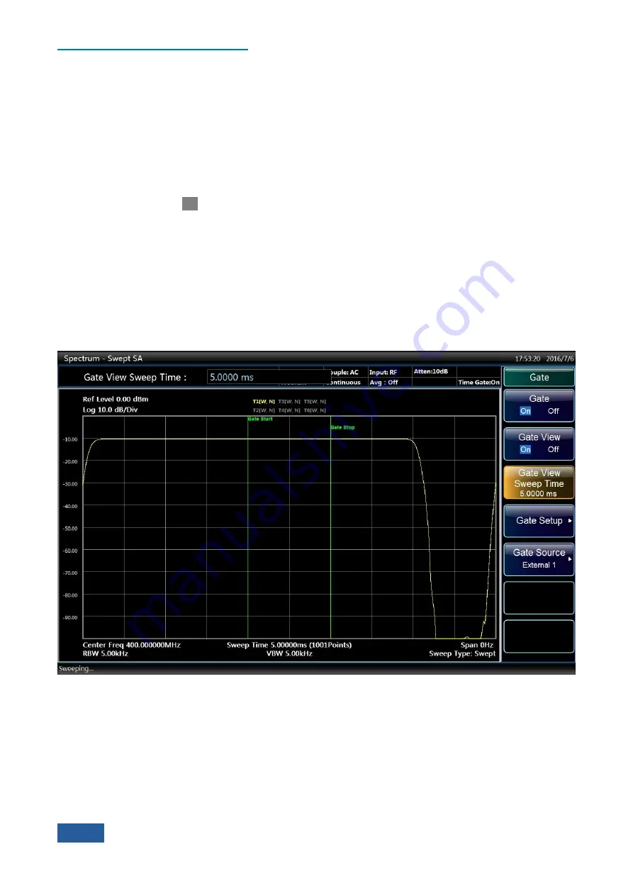
The interface of Gate Preview Window is shown in Fig. 4.58, stating the temporal relations of the gate trigger,
gate delay, width and the measured signal pulse envelope. The time on the left of the figure is the Zero Hour,
indicating the time when the gate trigger event occurs, which also refer to the initial time of the Gate On when
the gate delay is zero. The green line on the left represents the initial time of Gate On, as well as the gate delay
time. The time between the two green lines refers to the gate width, namely the gating time. The yellow path
line represents the temporal envelope of the input RF pulse signal.
Adjust the gate delay time to make the gating time between 20% and 80% of the pulse envelope. If there are
changes in the measuring conditions, such as the resolution bandwidth and bandwidth, etc., the Gate Preview
should be reopened to reset the gate trigger polarity, gate delay and gate width, etc.
Fig. 4.58 Gate Preview Interface of LO Status
Summary of Contents for 4051 Series
Page 5: ......
Page 6: ......
Page 7: ......
Page 14: ......
Page 18: ......
Page 68: ......
Page 225: ...5 Menu 5 1 Menu structure 211 5 1 3 13 Maker Mkr Fig 5 3 13 Marker Menu...
Page 241: ...5 Menu 5 1 Menu structure 227 5 1 4 13 Maker Mkr Fig 5 4 13 Marker Menu...
Page 259: ...5 Menu 5 1 Menu structure 245 5 1 5 13 Maker Mkr Fig 5 5 13 Marker Menu...
Page 266: ...5 Menu 5 1 Menu structure 252 5 1 6 5 Sweep Sweep Fig 5 6 5 Sweep Menu...
Page 275: ...5 Menu 5 1 Menu structure 261 5 1 6 13 Maker Mkr Fig 5 6 13 Marker Menu...
Page 277: ...5 Menu 5 1 Menu structure 263 5 1 6 15 Peak Search Peak Search Fig 5 6 15 Peak Search Menu...
Page 280: ...5 Menu 5 1 Menu structure 266 5 1 7 3 Span X Scale Span Fig 5 7 3 Span Menu...
Page 291: ...5 Menu 5 1 Menu structure 277 5 1 7 13 Maker Mkr Fig 5 7 13 Marker Menu...
Page 296: ...5 Menu 5 1 Menu structure 282 5 1 8 3 Span X Scale Span Fig 5 8 3 Span Menu...
Page 306: ...5 Menu 5 1 Menu structure 292 5 1 8 12 Marker Marker Fig 5 8 12 Marker Menu...
Page 307: ...5 Menu 5 1 Menu structure 293 5 1 8 13 Maker Mkr Fig 5 8 13 Marker Menu...
Page 309: ...5 Menu 5 1 Menu structure 295 5 1 8 15 Peak Search Peak Search Fig 5 8 15 Peak Search Menu...
Page 312: ...5 Menu 5 1 Menu structure 298 5 1 9 3 Span X Scale Span Span 4 000000 GHz Fig 5 9 3 Span Menu...
Page 323: ...5 Menu 5 1 Menu structure 309 5 1 9 13 Maker Mkr Fig 5 9 13 Marker Menu...
Page 328: ...5 Menu 5 1 Menu structure 314 5 1 10 3 Span X Scale Span Fig 5 10 3 Span Menu...
Page 329: ...5 Menu 5 1 Menu structure 315 5 1 10 4 Bandwidth BW Fig 5 10 4 Bandwidth Menu...
Page 333: ...5 Menu 5 1 Menu structure 319 5 1 10 7 Trace Trace Fig 5 10 7 Trace Menu...
Page 340: ...5 Menu 5 1 Menu structure 326 5 1 10 13 Maker Mkr Fig 5 10 13 Marker Menu...
Page 345: ...5 Menu 5 1 Menu structure 331 5 1 11 3 Span X Scale Span Fig 5 11 3 Span Menu...
Page 357: ...5 Menu 5 1 Menu structure 343 5 1 11 13 Maker Mkr Fig 5 11 13 Marker Menu...
Page 359: ...5 Menu 5 1 Menu structure 345 5 1 11 15 Peak Search Peak Search Fig 5 11 15 Peak Search Menu...
Page 656: ......


