User Manual
i Series / iX Series
43
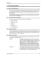
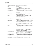
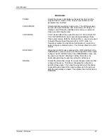
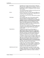
The following top-level menu choices can be accessed from the MENU key:
Entry
Description
MENU 1
PROGRAM
The PROGRAM menu allows output parameters the be
changed.
MEASUREMENTS
The MEASUREMENTS screens are not menus in that no user
entries are required.
TRANSIENTS
The TRANSIENTS menu allows output transients to be
programmed.
WAVEFORMS
The WAVEFORMS menu allows different waveforms to be
selected from the waveform library.
MORE
The MORE selection causes the second part of the MENU
screen to be displayed. (MENU 2)
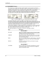
MENU 2
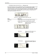
ADVANCED MEAS.
The ADVANCED MEAS. screens are for display only. No user
entries are required.
APPLICATIONS
The APPLICATIONS menu provides access to the optional
firmware application programs that may be installed in the i/iX
Series AC source.
SETUP REGISTERS
The SETUP REGISTERS menu allows complete instrument
settings and transient list programs to be saved to nonvolatile
memory.
MORE
The MORE selection causes the third part of the MENU screen
to be displayed. (MENU 3)
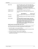
MENU 3
UTILITY
The UTILITY menu provides access to less commonly used
setup screens such as those for the GPIB and RS232C
interface settings, initial startup values, etc.
OUTPUT IMPEDANCE
The OUTPUT IMPEDANCE menu provides control of the AC
source output impedance. (Available only on 3001iX, 5001iX,
9003iX and 15003iX models. On systems with
–MODE-iX
option, only available when in 3 phase mode.)
MEASUREMENT CAL
The MEASUREMENT CAL menu allows for calibration of the
AC source measurement system.
OUTPUT CAL
The OUTPUT CAL menu allows for calibration of the AC source
output.
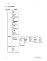
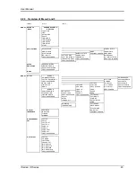
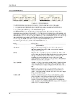
Following the Menu overview pages is a detailed description of each menu and sub menu.
Summary of Contents for 10001i
Page 2: ......
Page 3: ......
Page 6: ...ii This page intentionally left blank...
Page 38: ...User Manual 24 i Series iX Series Figure 3 5 Rear Panel View for the 3001i 3001iX...
Page 39: ...User Manual i Series iX Series 25 Figure 3 6 Rear Panel View for the 5001i 5001iX...
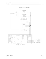
Page 43: ...User Manual i Series iX Series 29 Figure 3 8 Functional Test Setup...
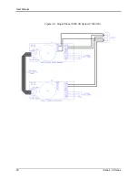
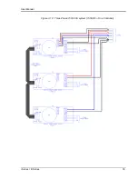
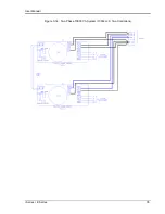
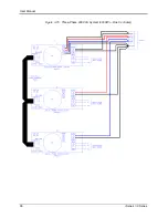
Page 44: ...User Manual 30 i Series iX Series Figure 3 9 Single Phase 10000 VA System 10001iX i...
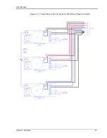
Page 46: ...User Manual 32 i Series iX Series Figure 3 11 Single Phase 15000 VA System 15001iX i...
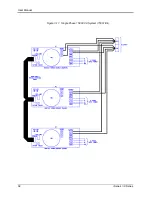
Page 48: ...User Manual 34 i Series iX Series Figure 3 13 Connection With MODE Option...
Page 118: ...User Manual 104 i Series iX Series Figure 5 2 Power Source Module Block Diagram...
Page 121: ...User Manual i Series iX Series 107 Figure 5 3 5001i Internal Layout...
Page 122: ...User Manual 108 i Series iX Series Figure 5 4 Logic Board LED s...
Page 124: ...User Manual 110 i Series iX Series Figure 5 5 AC Power Stage Layout...
Page 125: ...User Manual i Series iX Series 111 Figure 5 6 AC Control Logic Block Diagram...
Page 138: ...User Manual 124 i Series iX Series Figure 6 3 Adjustment Location...
Page 152: ...User Manual 138 i Series iX Series Figure 9 4 Voltage Modulation...
Page 219: ...User Manual i Series iX Series 205 Figure 9 36 Example Connection With 5001iX and EOS 1...
Page 221: ...User Manual i Series iX Series 207 Figure 9 38 15003iX CTS EOS3 LR3...
Page 222: ...User Manual 208 i Series iX Series Figure 9 39 15003iX 3 EOS3...
Page 233: ...User Manual i Series iX Series 219 Figure 9 41 Example Connection With MODE iX...
Page 240: ...User Manual 226 i Series iX Series Figure 9 42 Example Connections With OMNI 1 18i...
Page 241: ...User Manual i Series iX Series 227 Figure 9 43 Example Connections With OMNI 3 18i...

