User Manual
i Series / iX Series
69
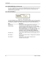
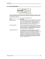
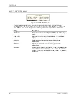
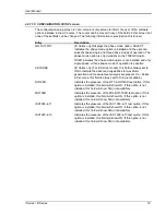
4.2.11.2 VOLTAGE/CURRENT CONTROL SETUP menu
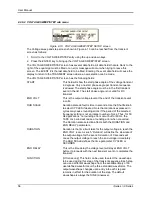
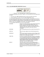
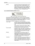
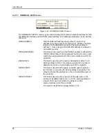
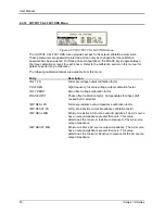
Figure 4-22: VOLTAGE/CURRENT CONTROL SETUP menu
The VOLTAGE/CURRENT CONTROL SETUP menu may be used to set output voltage and
current control parameters. These parameters are not frequently changed in the normal
operation of the AC source and are thus located on the UTILITY rather than the PROGRAM
menu.
The following options are available in this menu:
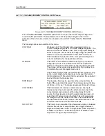
VOLT PAIR
[
iX Series only
] The iX Series can be operated in either a
135/270 voltage range pair or a 150/300 voltage range pair. The
amount of current available in the 135/270 range pair setting is
about 10% higher. Unless the extra voltage range is needed, the
maximum current can be attained in the 135/270 volt mode.
This field allows the selection of the most optimal voltage and
current combination for the application at hand.
OL MODE
This field is used to select constant current (CC) or constant
voltage (CV) mode. The constant current mode will limit the
maximum amount of current drawn by the load to the set value.
The voltage will be reduced as needed after the trip delay time
to maintain the level of programmed current.
The constant voltage mode will maintain the set voltage as long
as the current drawn by the load does not exceed the current
limit programmed. If the current limit is exceeded, the output will
be shut off after the trip delay time.
TRIP DELAY
The trip delay field may be used to set the amount of time to
hold off the current limit trip point. The minimum amount of time
is 100 ms or 0.1 sec. The maximum amount of time is 5.00 sec.
VOLT SENSE
This field selects the internal or external sense line inputs.
Internal sense does not require the external sense lines to be
connected as sensing occurs at the output relay of the AC
source. For best results, connect the external sense lines and
select the EXT sense mode in this field. This will compensate
for voltage drop in the cables to the load. The measurements
are also taken at the sense points, so the external sense mode
should be used for best measurement results.
NO. OUTPUT
This field is only accessible if the phase mode option is installed.
It allows the number of output phases to be toggled between
single and three phase mode. In single phase mode, all power is
available on phase A. The Mode-iX option is available to route
all power to a single output terminal pair.
Summary of Contents for 10001i
Page 2: ......
Page 3: ......
Page 6: ...ii This page intentionally left blank...
Page 38: ...User Manual 24 i Series iX Series Figure 3 5 Rear Panel View for the 3001i 3001iX...
Page 39: ...User Manual i Series iX Series 25 Figure 3 6 Rear Panel View for the 5001i 5001iX...
Page 43: ...User Manual i Series iX Series 29 Figure 3 8 Functional Test Setup...
Page 44: ...User Manual 30 i Series iX Series Figure 3 9 Single Phase 10000 VA System 10001iX i...
Page 46: ...User Manual 32 i Series iX Series Figure 3 11 Single Phase 15000 VA System 15001iX i...
Page 48: ...User Manual 34 i Series iX Series Figure 3 13 Connection With MODE Option...
Page 118: ...User Manual 104 i Series iX Series Figure 5 2 Power Source Module Block Diagram...
Page 121: ...User Manual i Series iX Series 107 Figure 5 3 5001i Internal Layout...
Page 122: ...User Manual 108 i Series iX Series Figure 5 4 Logic Board LED s...
Page 124: ...User Manual 110 i Series iX Series Figure 5 5 AC Power Stage Layout...
Page 125: ...User Manual i Series iX Series 111 Figure 5 6 AC Control Logic Block Diagram...
Page 138: ...User Manual 124 i Series iX Series Figure 6 3 Adjustment Location...
Page 152: ...User Manual 138 i Series iX Series Figure 9 4 Voltage Modulation...
Page 219: ...User Manual i Series iX Series 205 Figure 9 36 Example Connection With 5001iX and EOS 1...
Page 221: ...User Manual i Series iX Series 207 Figure 9 38 15003iX CTS EOS3 LR3...
Page 222: ...User Manual 208 i Series iX Series Figure 9 39 15003iX 3 EOS3...
Page 233: ...User Manual i Series iX Series 219 Figure 9 41 Example Connection With MODE iX...
Page 240: ...User Manual 226 i Series iX Series Figure 9 42 Example Connections With OMNI 1 18i...
Page 241: ...User Manual i Series iX Series 227 Figure 9 43 Example Connections With OMNI 3 18i...

