User Manual
266
i Series / iX Series
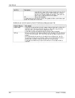
Sub-Tab
Description
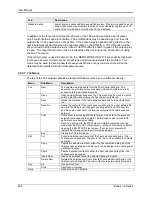
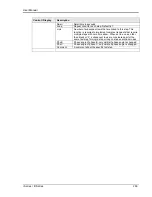
specifications. These limits must be entered manually into the
provided template file named “MS704_Distortion_Limits.ini”
located in the CIGui32 application directory. If the limits are
left at 0.00, no pass/fail criteria will be applied.
P/F
Pass or Fail indication.
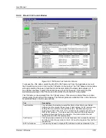
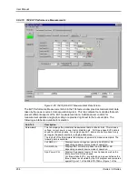
A phase selection is available to the left of the graphs and table, which allows each
phase to be displayed, one at a time.
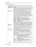
Additional user controls located on the EUT Performance Measurements Tab:
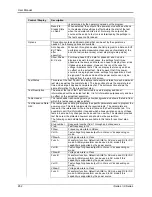
Control / Display
Description
Update Meas.
Triggers a new acquisition cycle and updates measurement data for all tabs. For
table SVF and TVF modes (Variable Frequency), data will be acquired at the
frequency set by the Test Frequency Dropdown control.
This button is always available regardless of what sub tab is selected.
Settings
Brings up a dialog box that allows scaling and color changes for the Waveform or
Current harmonics graphs. Note that setting changes will apply to graphs for all
phases.
For current harmonics graphs, only the absolute bar settings apply. The 704
measurement screen does not display relative current harmonic bar charts but
relative data is available in tabular format on the Cur Spectrum tab.
This button is available only if either the Waveforms or Cur Graph sub tab is
selected
Summary of Contents for 10001i
Page 2: ......
Page 3: ......
Page 6: ...ii This page intentionally left blank...
Page 38: ...User Manual 24 i Series iX Series Figure 3 5 Rear Panel View for the 3001i 3001iX...
Page 39: ...User Manual i Series iX Series 25 Figure 3 6 Rear Panel View for the 5001i 5001iX...
Page 43: ...User Manual i Series iX Series 29 Figure 3 8 Functional Test Setup...
Page 44: ...User Manual 30 i Series iX Series Figure 3 9 Single Phase 10000 VA System 10001iX i...
Page 46: ...User Manual 32 i Series iX Series Figure 3 11 Single Phase 15000 VA System 15001iX i...
Page 48: ...User Manual 34 i Series iX Series Figure 3 13 Connection With MODE Option...
Page 118: ...User Manual 104 i Series iX Series Figure 5 2 Power Source Module Block Diagram...
Page 121: ...User Manual i Series iX Series 107 Figure 5 3 5001i Internal Layout...
Page 122: ...User Manual 108 i Series iX Series Figure 5 4 Logic Board LED s...
Page 124: ...User Manual 110 i Series iX Series Figure 5 5 AC Power Stage Layout...
Page 125: ...User Manual i Series iX Series 111 Figure 5 6 AC Control Logic Block Diagram...
Page 138: ...User Manual 124 i Series iX Series Figure 6 3 Adjustment Location...
Page 152: ...User Manual 138 i Series iX Series Figure 9 4 Voltage Modulation...
Page 219: ...User Manual i Series iX Series 205 Figure 9 36 Example Connection With 5001iX and EOS 1...
Page 221: ...User Manual i Series iX Series 207 Figure 9 38 15003iX CTS EOS3 LR3...
Page 222: ...User Manual 208 i Series iX Series Figure 9 39 15003iX 3 EOS3...
Page 233: ...User Manual i Series iX Series 219 Figure 9 41 Example Connection With MODE iX...
Page 240: ...User Manual 226 i Series iX Series Figure 9 42 Example Connections With OMNI 1 18i...
Page 241: ...User Manual i Series iX Series 227 Figure 9 43 Example Connections With OMNI 3 18i...

