User Manual
320
i Series / iX Series
10. Error Messages
Any errors that occur during operation from either the front panel or the remote control interface
will result in error messages. Error messages are displayed in the upper left hand corner of the
LCD display. They are also stored in the error message queue from which they can be queried
using the SYST:ERR? Query. The error queue has a finite depth. If more error messages are
generated than can be held in the queue, a queue overflow message will be put in the last queue
location. To empty the queue, use the error query until the No Error result is received.
Errors appearing on the LCD will generally remain visible until the user moves to another screen.
If multiple error messages are generated in succession, only the last message will be visible as
there is only space for one error message on the LCD display.
The same area of the display is also used to display status messages. While error messages
always have a negative error number, status messages have a positive number.
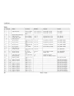
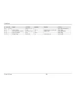
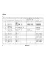
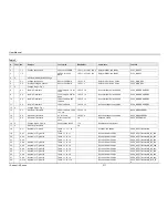
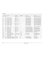
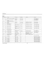
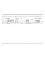
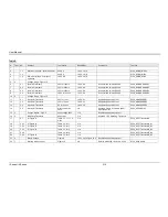
The table below displays a list of possible error and status messages along with their possible
cause and remedy.
Number
Message String
Cause
Remedy
0
"No error"
No errors in queue
-100
"Command error"
Unable to complete
requested operation
Unit may be in a mode inconsistent
with request.
-102
"Syntax error"
Command syntax
incorrect.
Misspelled or unsupported command
-103
"Invalid separator"
SCPI separator not
recognized
See SCPI section of programming
manual.
-104
"Data type error"
Data type invaled.
Check command for supported data
types
-108
"Parameter not
allowed"
One or more
additional parameters
were received.
Check programming manual for
correct number of parameters
-109
"Missing parameter"
Too few parameters
received for
requested operation
Check programming manual for
correct number of parameters
-110
"Command header
error"
Command header
incorrect
Check syntax of command.
-111
"header separator
error"
Invalid command
separator used.
Use semi-colon to separate
command headers
-112
"Program mnemonic
too long"
Syntax error
Check programming manual for
correct command syntax
-113
"Undefined header"
Command not
recognized error
Check programming manual for
correct command syntax
-120
"Numeric data error"
Data received is not
a number
Check programming manual for
correct command syntax
-121
"Invalid character in
number"
Number received
contains non-numeric
character(s)
Check programming manual for
correct command syntax
-123
"Exponent too large"
Exponent in number
exceeds limits
Check programming manual for
correct parameter range
-128
"Numeric data not
allowed"
Number received
when number is not
allowed.
Check programming manual for
correct command syntax
-168
"Block data not
Block data was sent.
Check programming manual for
Summary of Contents for 10001i
Page 2: ......
Page 3: ......
Page 6: ...ii This page intentionally left blank...
Page 38: ...User Manual 24 i Series iX Series Figure 3 5 Rear Panel View for the 3001i 3001iX...
Page 39: ...User Manual i Series iX Series 25 Figure 3 6 Rear Panel View for the 5001i 5001iX...
Page 43: ...User Manual i Series iX Series 29 Figure 3 8 Functional Test Setup...
Page 44: ...User Manual 30 i Series iX Series Figure 3 9 Single Phase 10000 VA System 10001iX i...
Page 46: ...User Manual 32 i Series iX Series Figure 3 11 Single Phase 15000 VA System 15001iX i...
Page 48: ...User Manual 34 i Series iX Series Figure 3 13 Connection With MODE Option...
Page 118: ...User Manual 104 i Series iX Series Figure 5 2 Power Source Module Block Diagram...
Page 121: ...User Manual i Series iX Series 107 Figure 5 3 5001i Internal Layout...
Page 122: ...User Manual 108 i Series iX Series Figure 5 4 Logic Board LED s...
Page 124: ...User Manual 110 i Series iX Series Figure 5 5 AC Power Stage Layout...
Page 125: ...User Manual i Series iX Series 111 Figure 5 6 AC Control Logic Block Diagram...
Page 138: ...User Manual 124 i Series iX Series Figure 6 3 Adjustment Location...
Page 152: ...User Manual 138 i Series iX Series Figure 9 4 Voltage Modulation...
Page 219: ...User Manual i Series iX Series 205 Figure 9 36 Example Connection With 5001iX and EOS 1...
Page 221: ...User Manual i Series iX Series 207 Figure 9 38 15003iX CTS EOS3 LR3...
Page 222: ...User Manual 208 i Series iX Series Figure 9 39 15003iX 3 EOS3...
Page 233: ...User Manual i Series iX Series 219 Figure 9 41 Example Connection With MODE iX...
Page 240: ...User Manual 226 i Series iX Series Figure 9 42 Example Connections With OMNI 1 18i...
Page 241: ...User Manual i Series iX Series 227 Figure 9 43 Example Connections With OMNI 3 18i...

