


User Manual
i Series / iX Series
65
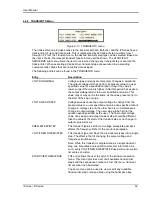
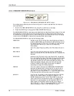
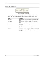
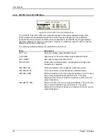
4.2.10 SETUP REGISTERS Menu
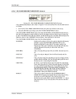
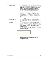
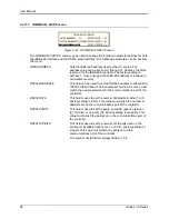
Figure 4-19: SETUP REGISTERS menu
The SETUP REGISTERS menu allows the user to store and recall complete instrument setups,
including transient program lists. A total of 8 non volatile setup registers is available, numbered
sequentially from 0 through 7.
The following entries can be found in the SETUP REGISTERS menu:
Entry
Description
SAVE REGISTER
Save present instrument setup to a register number selected by
the user. The numeric data entry keypad should be used to
enter a number between 0 and 7. Once the ENTER key is
pressed, all settings are saved. A message will appear at the
bottom of the screen to confirm the save operation.
RECALL REGISTER
Recall instrument setup from a register number selected by the
user. The numeric data entry keypad should be used to enter a
number between 0 and 7. Once the ENTER key is pressed, all
settings are recalled. A message will appear at the bottom of
the screen to confirm the recall operation.
VIEW/EDIT REGISTER
The View/Edit entry can be used to display the contents of a
setup register before it is recalled. After the user enters a
register number to view or edit and presses the ENTER key, the
PROGRAM screen will appear. All parameters that will be
changed by recalling the register will be blinking. If ENTER is
pressed again, the register will be recalled and the new values
take effect. To edit the register content, change all parameters
that need to be changed. Pressing ENTER will save the new
values and make them active.
Summary of Contents for 10001i
Page 2: ......
Page 3: ......
Page 6: ...ii This page intentionally left blank...
Page 38: ...User Manual 24 i Series iX Series Figure 3 5 Rear Panel View for the 3001i 3001iX...
Page 39: ...User Manual i Series iX Series 25 Figure 3 6 Rear Panel View for the 5001i 5001iX...
Page 43: ...User Manual i Series iX Series 29 Figure 3 8 Functional Test Setup...
Page 44: ...User Manual 30 i Series iX Series Figure 3 9 Single Phase 10000 VA System 10001iX i...
Page 46: ...User Manual 32 i Series iX Series Figure 3 11 Single Phase 15000 VA System 15001iX i...
Page 48: ...User Manual 34 i Series iX Series Figure 3 13 Connection With MODE Option...
Page 118: ...User Manual 104 i Series iX Series Figure 5 2 Power Source Module Block Diagram...
Page 121: ...User Manual i Series iX Series 107 Figure 5 3 5001i Internal Layout...
Page 122: ...User Manual 108 i Series iX Series Figure 5 4 Logic Board LED s...
Page 124: ...User Manual 110 i Series iX Series Figure 5 5 AC Power Stage Layout...
Page 125: ...User Manual i Series iX Series 111 Figure 5 6 AC Control Logic Block Diagram...
Page 138: ...User Manual 124 i Series iX Series Figure 6 3 Adjustment Location...
Page 152: ...User Manual 138 i Series iX Series Figure 9 4 Voltage Modulation...
Page 219: ...User Manual i Series iX Series 205 Figure 9 36 Example Connection With 5001iX and EOS 1...
Page 221: ...User Manual i Series iX Series 207 Figure 9 38 15003iX CTS EOS3 LR3...
Page 222: ...User Manual 208 i Series iX Series Figure 9 39 15003iX 3 EOS3...
Page 233: ...User Manual i Series iX Series 219 Figure 9 41 Example Connection With MODE iX...
Page 240: ...User Manual 226 i Series iX Series Figure 9 42 Example Connections With OMNI 1 18i...
Page 241: ...User Manual i Series iX Series 227 Figure 9 43 Example Connections With OMNI 3 18i...