User Manual
i Series / iX Series
189
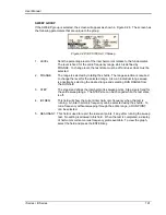
EUT CLASS
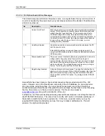
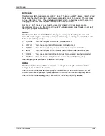
This field selects the desired product or EUT class. There are four EUT classes. Class 1, 2 and
3 are predefined by the standard and its level parameters cannot be changed. The user class
can be edited at any time. Changing between class 2 and 3 can be done while the state is on.
Changing to the user class requires the state to be in the off position.
For Class 1 EUT, the user class must be used. Only class 2 and 3 test levels are pre-
programmed. When using the provided, Cigui32 Windows program, class 1 tests are set up by
the Cigui32 program automatically.
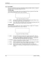
GROUP
This field selects the test GROUP. Selecting a group is required for editing the data fields
associated with the group as well as running the individual group if run group is selected. The
field has the following groups:
1. FCURVE
This is the first part of harmonic combination test.
2. OSWING This is the second part of harmonic combination test.
3. SWEEP
This is the sweep in frequency and resonance frequency detection.
4. HRAM
This is the first part of the Individual harmonics and inter harmonics test.
5. IHARM
This is the second part of the Individual harmonics and inter harmonics test.
6. MCURVE This is the Meister test. (Firmware revision 2.37 or higher required)
See the appropriate sections for details on each group.
DWELL
This field will show the dwell time in seconds for each group during the test and will allow
changes to the dwell time to be made.
The dwell time for the Meister curve group is the dwell time for each inter harmonics. This
combined with the frequency step size results in a 5-minute test time per frequency decade.
The dwell time for the sweep group is the dwell time for each frequency decade.
Summary of Contents for 10001i
Page 2: ......
Page 3: ......
Page 6: ...ii This page intentionally left blank...
Page 38: ...User Manual 24 i Series iX Series Figure 3 5 Rear Panel View for the 3001i 3001iX...
Page 39: ...User Manual i Series iX Series 25 Figure 3 6 Rear Panel View for the 5001i 5001iX...
Page 43: ...User Manual i Series iX Series 29 Figure 3 8 Functional Test Setup...
Page 44: ...User Manual 30 i Series iX Series Figure 3 9 Single Phase 10000 VA System 10001iX i...
Page 46: ...User Manual 32 i Series iX Series Figure 3 11 Single Phase 15000 VA System 15001iX i...
Page 48: ...User Manual 34 i Series iX Series Figure 3 13 Connection With MODE Option...
Page 118: ...User Manual 104 i Series iX Series Figure 5 2 Power Source Module Block Diagram...
Page 121: ...User Manual i Series iX Series 107 Figure 5 3 5001i Internal Layout...
Page 122: ...User Manual 108 i Series iX Series Figure 5 4 Logic Board LED s...
Page 124: ...User Manual 110 i Series iX Series Figure 5 5 AC Power Stage Layout...
Page 125: ...User Manual i Series iX Series 111 Figure 5 6 AC Control Logic Block Diagram...
Page 138: ...User Manual 124 i Series iX Series Figure 6 3 Adjustment Location...
Page 152: ...User Manual 138 i Series iX Series Figure 9 4 Voltage Modulation...
Page 219: ...User Manual i Series iX Series 205 Figure 9 36 Example Connection With 5001iX and EOS 1...
Page 221: ...User Manual i Series iX Series 207 Figure 9 38 15003iX CTS EOS3 LR3...
Page 222: ...User Manual 208 i Series iX Series Figure 9 39 15003iX 3 EOS3...
Page 233: ...User Manual i Series iX Series 219 Figure 9 41 Example Connection With MODE iX...
Page 240: ...User Manual 226 i Series iX Series Figure 9 42 Example Connections With OMNI 1 18i...
Page 241: ...User Manual i Series iX Series 227 Figure 9 43 Example Connections With OMNI 3 18i...

