


User Manual
84
i Series / iX Series
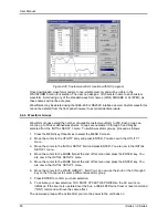
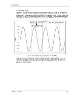
the MEAS key may not always bring up the selected screen immediately. There will be a
perceptible delay. This will prevent the screen from appearing with invalid or blank readouts.
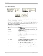
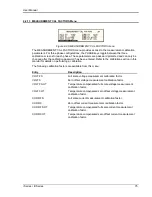
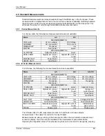
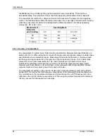
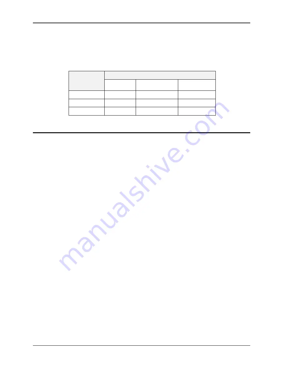
The measurement method for voltage and current will depend on the power source operating
mode. The following table shows the return value type (rms or average) and method of coupling
when the measurement command is initiated with a different extension at various operating
modes (AC, DC or AC + DC).
Measurement
Extension
and Coupling
Operating Mode
AC
DC
AC + DC
AC
rms
rms
rms
DC
rms
rms
average
Coupling
AC
DC
DC
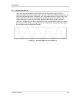
4.5.3 Accuracy Considerations
Any measurement system has a finite accuracy specification. Measurement specifications are
listed in Section 2. When using the AC source for measurement purposes, always consider these
specifications when interpreting results. Measurement inaccuracies become more pronounced
as the signal being measured is at the low end of the measurement range. This is particularly
relevant for low current measurements. The i and iX Series are high power AC sources
optimized for providing and measuring high load currents. When powering low power loads,
measurement inaccuracies on rms and peak current measurements will greatly affect derived
measurements such as power, power factor and crest factor.
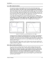
The measurement system on the i and iX Series uses a data acquisition system with a 20 kHz
bandwidth. This means that high frequency components of the measured signal are filtered out.
Any contribution to the rms value of voltage and current above this cutoff frequency will not be
reflected in the i and iX Series measurements. When using an external measurement reference,
this may account for discrepancies in readings.
Summary of Contents for 10001i
Page 2: ......
Page 3: ......
Page 6: ...ii This page intentionally left blank...
Page 38: ...User Manual 24 i Series iX Series Figure 3 5 Rear Panel View for the 3001i 3001iX...
Page 39: ...User Manual i Series iX Series 25 Figure 3 6 Rear Panel View for the 5001i 5001iX...
Page 43: ...User Manual i Series iX Series 29 Figure 3 8 Functional Test Setup...
Page 44: ...User Manual 30 i Series iX Series Figure 3 9 Single Phase 10000 VA System 10001iX i...
Page 46: ...User Manual 32 i Series iX Series Figure 3 11 Single Phase 15000 VA System 15001iX i...
Page 48: ...User Manual 34 i Series iX Series Figure 3 13 Connection With MODE Option...
Page 118: ...User Manual 104 i Series iX Series Figure 5 2 Power Source Module Block Diagram...
Page 121: ...User Manual i Series iX Series 107 Figure 5 3 5001i Internal Layout...
Page 122: ...User Manual 108 i Series iX Series Figure 5 4 Logic Board LED s...
Page 124: ...User Manual 110 i Series iX Series Figure 5 5 AC Power Stage Layout...
Page 125: ...User Manual i Series iX Series 111 Figure 5 6 AC Control Logic Block Diagram...
Page 138: ...User Manual 124 i Series iX Series Figure 6 3 Adjustment Location...
Page 152: ...User Manual 138 i Series iX Series Figure 9 4 Voltage Modulation...
Page 219: ...User Manual i Series iX Series 205 Figure 9 36 Example Connection With 5001iX and EOS 1...
Page 221: ...User Manual i Series iX Series 207 Figure 9 38 15003iX CTS EOS3 LR3...
Page 222: ...User Manual 208 i Series iX Series Figure 9 39 15003iX 3 EOS3...
Page 233: ...User Manual i Series iX Series 219 Figure 9 41 Example Connection With MODE iX...
Page 240: ...User Manual 226 i Series iX Series Figure 9 42 Example Connections With OMNI 1 18i...
Page 241: ...User Manual i Series iX Series 227 Figure 9 43 Example Connections With OMNI 3 18i...