User Manual
i Series / iX Series
179
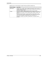
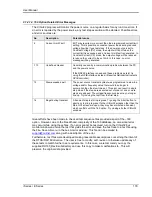
9.1.2.14 160 Option Related Error Messages
The CIGui32 program will monitor the power source on a regular basis for any run time errors. If
an error is reported by the power source, any test step execution will be aborted. Possible errors
and error sources are:
No
Description
Potential cause
2
Current Limit Fault
EUT may require more current than the programmed current limit
setting. This is possible on constant power loads during reduced
voltage (low line) type test steps. If the power source is set to
Constant Voltage (CV) mode, the output will trip off when the
current limit is exceeded and a Current Limit fault is generated. In
Constant Current (CC) mode, the output voltage will be reduced
to reduce the current to the set limit. In this case, no error
message will be generated.
-113
Undefined Header
Generally caused by a communication problem between the PC
and the power source.
If the RS232 interface is used and these problems persist, try
using the GPIB interface instead. (Requires National Instruments
GPIB controller).
15
Slew exceeds dwell
The power source transient system was programmed to slew to a
voltage and/or frequency value that would take longer to
accomplish than the slew time set. This error can result in single
step mode if the steps are executed out of order or one or more
steps are skipped. The voltage/frequency values may no longer
line up. Try running the test from the first step.
16
Illegal during transient
A transient step is still in progress. Try using the Abort button to
abort any test in progress. If other CIGui32 screens other than the
Main GUI screen are open, they may have initiated a transient,
which conflicts with the 160 option. Try closing all other CIGui32
windows.
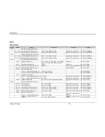
Great efforts have been made to check all test sequence files provided as part of the
–160
option. However, due to the breadth and complexity of the 160 database, an occasional error
may occur while using these files. If an error cannot be resolved, turn on the CIGui32 bus
monitor window and rerun the test that yields the error and save the bus trace to a text file using
the File, Save All menu in the bus monitor window. This file can be emailed to
along with a description of the error.
Furthermore, test files were developed making reasonable assumptions concerning the intent of
the RTCA/DO-160 directive. The user is free to modify, edit, revise or otherwise update any of
these tests to match his/her own requirements. In this case, we recommend you copy the
supplied DO160_RevE subdirectory and use this copy to make modifications to. This will
preserve the original data provided.
Summary of Contents for 10001i
Page 2: ......
Page 3: ......
Page 6: ...ii This page intentionally left blank...
Page 38: ...User Manual 24 i Series iX Series Figure 3 5 Rear Panel View for the 3001i 3001iX...
Page 39: ...User Manual i Series iX Series 25 Figure 3 6 Rear Panel View for the 5001i 5001iX...
Page 43: ...User Manual i Series iX Series 29 Figure 3 8 Functional Test Setup...
Page 44: ...User Manual 30 i Series iX Series Figure 3 9 Single Phase 10000 VA System 10001iX i...
Page 46: ...User Manual 32 i Series iX Series Figure 3 11 Single Phase 15000 VA System 15001iX i...
Page 48: ...User Manual 34 i Series iX Series Figure 3 13 Connection With MODE Option...
Page 118: ...User Manual 104 i Series iX Series Figure 5 2 Power Source Module Block Diagram...
Page 121: ...User Manual i Series iX Series 107 Figure 5 3 5001i Internal Layout...
Page 122: ...User Manual 108 i Series iX Series Figure 5 4 Logic Board LED s...
Page 124: ...User Manual 110 i Series iX Series Figure 5 5 AC Power Stage Layout...
Page 125: ...User Manual i Series iX Series 111 Figure 5 6 AC Control Logic Block Diagram...
Page 138: ...User Manual 124 i Series iX Series Figure 6 3 Adjustment Location...
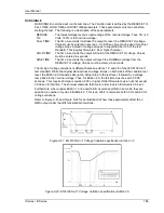
Page 152: ...User Manual 138 i Series iX Series Figure 9 4 Voltage Modulation...
Page 219: ...User Manual i Series iX Series 205 Figure 9 36 Example Connection With 5001iX and EOS 1...
Page 221: ...User Manual i Series iX Series 207 Figure 9 38 15003iX CTS EOS3 LR3...
Page 222: ...User Manual 208 i Series iX Series Figure 9 39 15003iX 3 EOS3...
Page 233: ...User Manual i Series iX Series 219 Figure 9 41 Example Connection With MODE iX...
Page 240: ...User Manual 226 i Series iX Series Figure 9 42 Example Connections With OMNI 1 18i...
Page 241: ...User Manual i Series iX Series 227 Figure 9 43 Example Connections With OMNI 3 18i...

