User Manual
i Series / iX Series
39
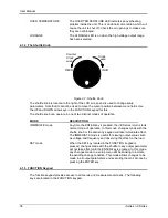
M ENU
PROG
WAVE
M EAS
OUTPUT
ON/OFF
PHASE
SET
+/-
FUNCTION
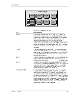
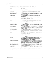
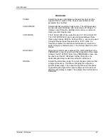
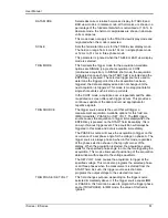
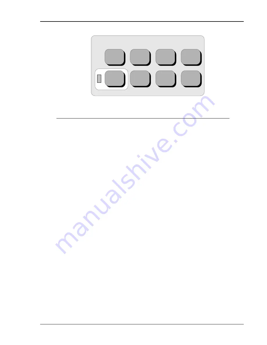
Figure 4-2: FUNCTION keypad
KEY
DESCRIPTION
MENU
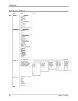
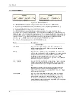
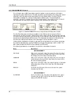
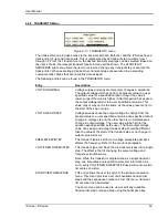
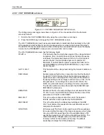
The top level menu is accessed by pressing the MENU key.
Three shortcut keys are used to provide direct access to the
PROGRAM, WAVEFORM, and MEASUREMENT screens as
these are among the most frequently used screens. Thus,
instead of going through the main menu to reach the
PROGRAM, WAVEFORM, and MEASUREMENT screens, they
can be accessed directly by pressing the PROG, WAVE, and
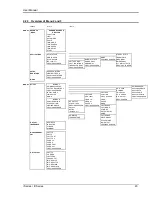
MEAS keys respectively. A map of the Main menus is provided
on the next few pages. There are three top-level menus in the
i/iX Series.
PROG
The PROG key is a shortcut to access the PROGRAM menu
directly. The PROGRAM menu is one of the most frequently
used menus. Thus, instead of going through the main menu to
reach the PROGRAM menu, it can be accessed directly by
pressing the PROG key.
WAVE
The WAVE key is a shortcut to access the WAVEFORM screen
directly. The WAVEFORM screen is used to select a user
defined arbitrary waveform.
(iX Series only)
MEAS
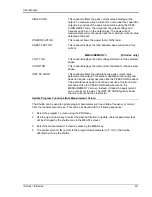
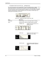
The MEAS key is a shortcut to access the MEASUREMENT
screen directly. The MEASUREMENT screen is one of the most
frequently used screens. Thus, instead of going through the
main menu to reach the MEASUREMENT screen, it can be
accessed directly by pressing the MEAS key.
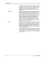
OUTPUT ON/OFF
The OUTPUT ON/OFF key toggles the output relay on or off.
The state of the output relay is reflected by the green LED
located directly to the left of the OUTPUT ON/OFF key. If the
green LED is lit, the output relay is enabled (closed) and the
programmed output voltage is present at the output terminals. If
the green LED is off, the output relay is open and both the HIGH
and LO terminal of the output terminal block are disconnected
from the power source. In this mode, the output is floating. The
ON/OFF button provides a convenient way to disconnect the
load without having to remove any wires.
Summary of Contents for 10001i
Page 2: ......
Page 3: ......
Page 6: ...ii This page intentionally left blank...
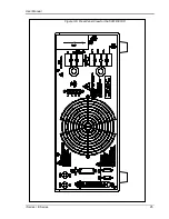
Page 38: ...User Manual 24 i Series iX Series Figure 3 5 Rear Panel View for the 3001i 3001iX...
Page 39: ...User Manual i Series iX Series 25 Figure 3 6 Rear Panel View for the 5001i 5001iX...
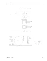
Page 43: ...User Manual i Series iX Series 29 Figure 3 8 Functional Test Setup...
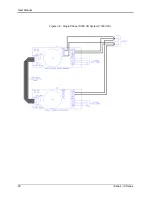
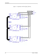
Page 44: ...User Manual 30 i Series iX Series Figure 3 9 Single Phase 10000 VA System 10001iX i...
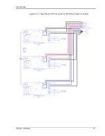
Page 46: ...User Manual 32 i Series iX Series Figure 3 11 Single Phase 15000 VA System 15001iX i...
Page 48: ...User Manual 34 i Series iX Series Figure 3 13 Connection With MODE Option...
Page 118: ...User Manual 104 i Series iX Series Figure 5 2 Power Source Module Block Diagram...
Page 121: ...User Manual i Series iX Series 107 Figure 5 3 5001i Internal Layout...
Page 122: ...User Manual 108 i Series iX Series Figure 5 4 Logic Board LED s...
Page 124: ...User Manual 110 i Series iX Series Figure 5 5 AC Power Stage Layout...
Page 125: ...User Manual i Series iX Series 111 Figure 5 6 AC Control Logic Block Diagram...
Page 138: ...User Manual 124 i Series iX Series Figure 6 3 Adjustment Location...
Page 152: ...User Manual 138 i Series iX Series Figure 9 4 Voltage Modulation...
Page 219: ...User Manual i Series iX Series 205 Figure 9 36 Example Connection With 5001iX and EOS 1...
Page 221: ...User Manual i Series iX Series 207 Figure 9 38 15003iX CTS EOS3 LR3...
Page 222: ...User Manual 208 i Series iX Series Figure 9 39 15003iX 3 EOS3...
Page 233: ...User Manual i Series iX Series 219 Figure 9 41 Example Connection With MODE iX...
Page 240: ...User Manual 226 i Series iX Series Figure 9 42 Example Connections With OMNI 1 18i...
Page 241: ...User Manual i Series iX Series 227 Figure 9 43 Example Connections With OMNI 3 18i...

