

User Manual
i Series / iX Series
119
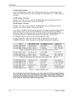
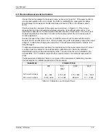
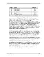
Note: The Fluke 8506A Digital Multimeter must be used for the following calibration. The
8506A must be set to the AC HI ACCUR mode for all AC measurements.
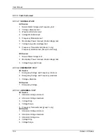
AC Volt Full-scale:
Program the output to the 300 volt range. Close the output relay. Program the output to 240 volts
and 60 Hz. Go to the MEASUREMENT CALIBRATION screen. Enter the actual AC output
voltage for the VOLT FS parameter and press the ENTER key.
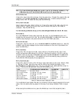
AC Current Full-scale:
Apply a load to the output. Refer to Table 6-2. Program the output to 150 volts on the 150 volt
range and 60 Hz. Observe the actual output current and enter this value for the CURR FS
parameter. Press the ENTER key.
For the following calibration steps put the external Digital Multimeter into the DC mode.
DC Volt Zero:
Go to the PROGRAM 2 screen and program the DC mode. Go the PROGRAM screen and
program the 300 range and +2.0 volts. Go to the MEASUREMENT CALIBRATION screen and
enter the value displayed on the external meter for the VOLT ZERO parameter.
DC Volt +Full-scale:
Program the output to +240 volts. Go to the MEASUREMENT CALIBRATION screen. Enter the
actual DC output voltage displayed on the external multimeter for the VOLT FS parameter and
press the ENTER key.
DC Current Zero:
Program the 150 volt range and 0 volts. Apply a 67 ohm, 270 watt load to the output. This
resistor will represent approximately a 2 amp load. Program the output to 135 volts. Enter the
actual DC load current for the CURR ZERO parameter in the MEASUREMENT CALIBRATION
screen and press the ENTER key. If this adjustment can‟t be successfully made, perform the
Current Monitor Offset Adjustment in paragraph 6.6.
DC Current Full-scale:
Program the output to 0 volts on the 150 range. Apply load resistor to the output. Refer to Table
5. Program 135 volts. Enter the actual output current for the CURR FS parameter in the
MEASUREMENT CALIBRATION screen. The value indicated by the External DVM is called V
ac
or V
DC
. The current measured by the current shunt is called I
ac
or I
DC
.
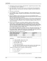
TITLE
PROGRAM/LOAD PARAMETERS
PARAMETER
ADJUST TO
AC Volt Full-scale
240 VAC, 60 Hz
VOLT FS
V
ac
AC Current Full-scale
150 Range, 150 VAC, full load
CURR FS
I
ac
DC Volt Zero
300 Range, +2.0 VDC
VOLT ZERO
V
DC
DC Volt + Full-scale
+240 VDC
VOLT FS
V
DC
DC Current Zero
150 Range, 135 VDC, 67 ohm load
CURR ZERO
I
DC
DC Current Full-scale
150 Range, 135 VDC, full load
CURR FS
I
DC
Table 6-3: Measurement Calibration Table
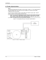
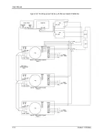
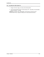
For a multi-phase power system that uses one controller, 15003iX, repeat paragraph 6.5 for each
phase. Move the external test equipment to the phase that is being calibrated. Refer to Figure
6-2.
While viewing the calibration screen, press the PHASE key to select the respective phase.
Summary of Contents for 10001i
Page 2: ......
Page 3: ......
Page 6: ...ii This page intentionally left blank...
Page 38: ...User Manual 24 i Series iX Series Figure 3 5 Rear Panel View for the 3001i 3001iX...
Page 39: ...User Manual i Series iX Series 25 Figure 3 6 Rear Panel View for the 5001i 5001iX...
Page 43: ...User Manual i Series iX Series 29 Figure 3 8 Functional Test Setup...
Page 44: ...User Manual 30 i Series iX Series Figure 3 9 Single Phase 10000 VA System 10001iX i...
Page 46: ...User Manual 32 i Series iX Series Figure 3 11 Single Phase 15000 VA System 15001iX i...
Page 48: ...User Manual 34 i Series iX Series Figure 3 13 Connection With MODE Option...
Page 118: ...User Manual 104 i Series iX Series Figure 5 2 Power Source Module Block Diagram...
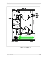
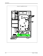
Page 121: ...User Manual i Series iX Series 107 Figure 5 3 5001i Internal Layout...
Page 122: ...User Manual 108 i Series iX Series Figure 5 4 Logic Board LED s...
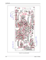
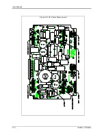
Page 124: ...User Manual 110 i Series iX Series Figure 5 5 AC Power Stage Layout...
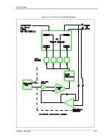
Page 125: ...User Manual i Series iX Series 111 Figure 5 6 AC Control Logic Block Diagram...
Page 138: ...User Manual 124 i Series iX Series Figure 6 3 Adjustment Location...
Page 152: ...User Manual 138 i Series iX Series Figure 9 4 Voltage Modulation...
Page 219: ...User Manual i Series iX Series 205 Figure 9 36 Example Connection With 5001iX and EOS 1...
Page 221: ...User Manual i Series iX Series 207 Figure 9 38 15003iX CTS EOS3 LR3...
Page 222: ...User Manual 208 i Series iX Series Figure 9 39 15003iX 3 EOS3...
Page 233: ...User Manual i Series iX Series 219 Figure 9 41 Example Connection With MODE iX...
Page 240: ...User Manual 226 i Series iX Series Figure 9 42 Example Connections With OMNI 1 18i...
Page 241: ...User Manual i Series iX Series 227 Figure 9 43 Example Connections With OMNI 3 18i...