User Manual
210
i Series / iX Series
9.4.6.2 Front Panel Controls/Indicators
Power Switch and Lamp
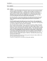
A power switch turns the EOS on or off. A lamp above the switch illuminates when power is on.
Active Lamp
This lamp is illuminated when the EOS is operating with the power transformer and electronic
switches active for IEC1000-4-11 testing. During normal power source operation the lamp is off.
Fault Lamp
This lamp is illuminated when an overtemperature or an overcurrent condition has occurred in
the EOS. If a fault occurs during IEC1000-4-11 testing, the FAULT lamp will be turned on and
the EOS electronic switches will be turned off. The next time the controlling power source
attempts to change the EOS state, the test will be aborted, the FAULT lamp will be turned off, the
controlling power source will indicate an EOS error, and the EOS unit will be programmed to
normal (bypassing EOS) mode.
The overtemperature condition will be released when the internal circuits have sufficiently cooled.
An overcurrent condition may be reset by reactivating the EOS option from the iX controller 4-11
option screen.
Tap Select Switch (Second generation EOS1 only)
The EOS1 tap selection between the 70% and the 80% dip level taps is made using a toggle
switch on the front panel of the EOS1. If this toggle switch is not present, the EOS1 is a first
generation version. See Table 9-21 for revision details.
To use the 70% dip level, set the toggle switch in the70% position.
To use the 80% dip level, set the toggle switch in the 80% position.
9.4.6.3 EOS1 70/80 Tap setting change
Second generation EOS1 units are equipped with both a 70% and an 80% output tap. The
default configuration shipped from the factor is set to the 70% tap. This is the most commonly
used dip level for product standards. However, Edition 2.0 of the IEC 61000-4-11 test standard
does allow for a 80% dip level for which the alternate tap setting may be used. The EOS1 tap
selection between the 70% and the 80% dip level taps is made using a toggle switch on the front
panel of the EOS1. If this toggle switch is not present, the EOS1 is a first generation version.
See Table 9-21 for revision details.
To use the 70% dip level, set the toggle switch in the70% position.
To use the 80% dip level, set the toggle switch in the 80% position.
Note: When using the Cigui32 Windows GUI program to run IEC 61000-4-11 tests, select
the EOS1 tap setting on the IEC 61000-4-11 test screen to match the toggle switch
position. The GUI has no way to determining the switch setting on its own. If set
correctly, the Cigui32 program will use the EOS when the correct dip level is
programmed in the voltage dips data grid.
Summary of Contents for 10001i
Page 2: ......
Page 3: ......
Page 6: ...ii This page intentionally left blank...
Page 38: ...User Manual 24 i Series iX Series Figure 3 5 Rear Panel View for the 3001i 3001iX...
Page 39: ...User Manual i Series iX Series 25 Figure 3 6 Rear Panel View for the 5001i 5001iX...
Page 43: ...User Manual i Series iX Series 29 Figure 3 8 Functional Test Setup...
Page 44: ...User Manual 30 i Series iX Series Figure 3 9 Single Phase 10000 VA System 10001iX i...
Page 46: ...User Manual 32 i Series iX Series Figure 3 11 Single Phase 15000 VA System 15001iX i...
Page 48: ...User Manual 34 i Series iX Series Figure 3 13 Connection With MODE Option...
Page 118: ...User Manual 104 i Series iX Series Figure 5 2 Power Source Module Block Diagram...
Page 121: ...User Manual i Series iX Series 107 Figure 5 3 5001i Internal Layout...
Page 122: ...User Manual 108 i Series iX Series Figure 5 4 Logic Board LED s...
Page 124: ...User Manual 110 i Series iX Series Figure 5 5 AC Power Stage Layout...
Page 125: ...User Manual i Series iX Series 111 Figure 5 6 AC Control Logic Block Diagram...
Page 138: ...User Manual 124 i Series iX Series Figure 6 3 Adjustment Location...
Page 152: ...User Manual 138 i Series iX Series Figure 9 4 Voltage Modulation...
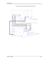
Page 219: ...User Manual i Series iX Series 205 Figure 9 36 Example Connection With 5001iX and EOS 1...
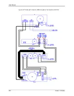
Page 221: ...User Manual i Series iX Series 207 Figure 9 38 15003iX CTS EOS3 LR3...
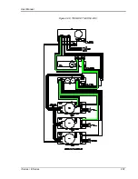
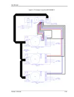
Page 222: ...User Manual 208 i Series iX Series Figure 9 39 15003iX 3 EOS3...
Page 233: ...User Manual i Series iX Series 219 Figure 9 41 Example Connection With MODE iX...
Page 240: ...User Manual 226 i Series iX Series Figure 9 42 Example Connections With OMNI 1 18i...
Page 241: ...User Manual i Series iX Series 227 Figure 9 43 Example Connections With OMNI 3 18i...

