User Manual
64
i Series / iX Series
4.2.8 ADVANCE MEAS. Menu [
iX Series only
]
This entry in the MENU 2 screen displays the HARMONICS/TRACE ANALYSIS screen which is
covered in section 4. This field can be used in lieu of the MEAS key to directly bring up the
advanced measurements screens.
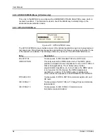
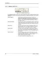
4.2.9 APPLICATIONS Menu
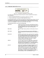
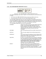
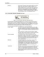
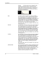
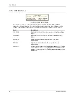
Figure 4-18: APPLICATIONS menu
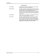
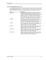
The APPLICATIONS menu provides access to the optional application specific pre-programmed
test sequences. Since these test sequences are optional, this menu may have no choices if none
of the options are installed. The following entries may be found in the APPLICATIONS menu:
Entry
Description
MIL-STD 704
Test sequence for MIL standard 704 AC and DC tests.
OMNI OPTION
This entry selects the OMNI control menu. The OMNI option
provides a lumped reference impedance for use in IEC 1000-3-3
Flicker test applications. The iX Series also provides
programmable impedance, so, in most cases, the OMNI option
is not required. For the i Series, the OMNI impedance is
available as an option. If the OMNI option is installed, this
screen allows the impedance to be ENGAGED or BYPASSED.
RTCA/DO-160
Test sequence for RTCA DO160 commercial aviation AC and
DC tests.
IEC-1000-4-11
Test sequences for IEC 1000-4-11 Voltage Dips and Variations
test standard.
IEC-1000-4-13
Test sequence for IEC 1000-4-13 Harmonics and
Interharmonics test standard.
Summary of Contents for 10001i
Page 2: ......
Page 3: ......
Page 6: ...ii This page intentionally left blank...
Page 38: ...User Manual 24 i Series iX Series Figure 3 5 Rear Panel View for the 3001i 3001iX...
Page 39: ...User Manual i Series iX Series 25 Figure 3 6 Rear Panel View for the 5001i 5001iX...
Page 43: ...User Manual i Series iX Series 29 Figure 3 8 Functional Test Setup...
Page 44: ...User Manual 30 i Series iX Series Figure 3 9 Single Phase 10000 VA System 10001iX i...
Page 46: ...User Manual 32 i Series iX Series Figure 3 11 Single Phase 15000 VA System 15001iX i...
Page 48: ...User Manual 34 i Series iX Series Figure 3 13 Connection With MODE Option...
Page 118: ...User Manual 104 i Series iX Series Figure 5 2 Power Source Module Block Diagram...
Page 121: ...User Manual i Series iX Series 107 Figure 5 3 5001i Internal Layout...
Page 122: ...User Manual 108 i Series iX Series Figure 5 4 Logic Board LED s...
Page 124: ...User Manual 110 i Series iX Series Figure 5 5 AC Power Stage Layout...
Page 125: ...User Manual i Series iX Series 111 Figure 5 6 AC Control Logic Block Diagram...
Page 138: ...User Manual 124 i Series iX Series Figure 6 3 Adjustment Location...
Page 152: ...User Manual 138 i Series iX Series Figure 9 4 Voltage Modulation...
Page 219: ...User Manual i Series iX Series 205 Figure 9 36 Example Connection With 5001iX and EOS 1...
Page 221: ...User Manual i Series iX Series 207 Figure 9 38 15003iX CTS EOS3 LR3...
Page 222: ...User Manual 208 i Series iX Series Figure 9 39 15003iX 3 EOS3...
Page 233: ...User Manual i Series iX Series 219 Figure 9 41 Example Connection With MODE iX...
Page 240: ...User Manual 226 i Series iX Series Figure 9 42 Example Connections With OMNI 1 18i...
Page 241: ...User Manual i Series iX Series 227 Figure 9 43 Example Connections With OMNI 3 18i...

