User Manual
i Series / iX Series
223
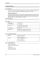
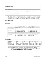
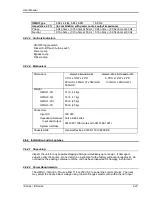
OMNI Type
1-18i, 3-18i, 1-37i, 3-37i
1-37iJ
Impedance ± 5%
(in combination with power source output impedance)
Phase
0.24 ohms + j 0.15 ohms at 50 Hz
0.24 ohms + j 0.062 ohms at 50 Hz
Neutral
0.16 ohms + j 0.10 ohms at 50 Hz
0.16 ohms + j 0.054 ohms at 50 Hz
9.6.3.3 Controls/Indicators
ON/OFF toggle switch
Flicker On/Off push button switch
Power Lamp
Bypass Lamp
Flicker Lamp
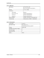
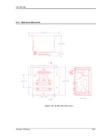
9.6.3.4 Mechanical
Dimensions
Omni 1-18i and 3-18i: Omni 1-37i, 1-37iJ and 3-37i:
3.5"H x 19"W x 22"D 5.25”H x 19”W x 22”D
89mmH x 480mmW x 560mmD 133mmH x 480mmW x
560mmD
Weight
OMNI-1-18i
OMNI-3-18i
OMNI-1-37iJ
OMNI-3-37i
31 lb. (14 kg)
37 lb. (17 kg)
55 lb. (25 kg)
55 lb. (25 kg)
Connectors
Input AC
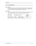
Impedance Network
Input and Output
System Interface
IEC 320
Kulka 9-85 series
3M 3367-1000 (mates with 3M 3366-1001)
Chassis Slide
General Devices C300S-118-U/B308 BK
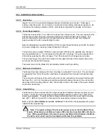
9.6.4 Installation and Acceptance
9.6.4.1 Unpacking
Inspect the unit for any possible shipping damage immediately upon receipt. If damage is
evident, notify the carrier. Do not return an instrument to the factory without prior approval. Do
not destroy the packing container until the unit has been inspected for damage in shipment.
9.6.4.2 Power Requirements
The OMNI 1-18i and 3-18i use either 115 or 230 VAC to power the control circuits. The user
may select the desired input voltage using the small range selector card within the IEC input
Summary of Contents for 10001i
Page 2: ......
Page 3: ......
Page 6: ...ii This page intentionally left blank...
Page 38: ...User Manual 24 i Series iX Series Figure 3 5 Rear Panel View for the 3001i 3001iX...
Page 39: ...User Manual i Series iX Series 25 Figure 3 6 Rear Panel View for the 5001i 5001iX...
Page 43: ...User Manual i Series iX Series 29 Figure 3 8 Functional Test Setup...
Page 44: ...User Manual 30 i Series iX Series Figure 3 9 Single Phase 10000 VA System 10001iX i...
Page 46: ...User Manual 32 i Series iX Series Figure 3 11 Single Phase 15000 VA System 15001iX i...
Page 48: ...User Manual 34 i Series iX Series Figure 3 13 Connection With MODE Option...
Page 118: ...User Manual 104 i Series iX Series Figure 5 2 Power Source Module Block Diagram...
Page 121: ...User Manual i Series iX Series 107 Figure 5 3 5001i Internal Layout...
Page 122: ...User Manual 108 i Series iX Series Figure 5 4 Logic Board LED s...
Page 124: ...User Manual 110 i Series iX Series Figure 5 5 AC Power Stage Layout...
Page 125: ...User Manual i Series iX Series 111 Figure 5 6 AC Control Logic Block Diagram...
Page 138: ...User Manual 124 i Series iX Series Figure 6 3 Adjustment Location...
Page 152: ...User Manual 138 i Series iX Series Figure 9 4 Voltage Modulation...
Page 219: ...User Manual i Series iX Series 205 Figure 9 36 Example Connection With 5001iX and EOS 1...
Page 221: ...User Manual i Series iX Series 207 Figure 9 38 15003iX CTS EOS3 LR3...
Page 222: ...User Manual 208 i Series iX Series Figure 9 39 15003iX 3 EOS3...
Page 233: ...User Manual i Series iX Series 219 Figure 9 41 Example Connection With MODE iX...
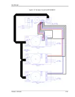
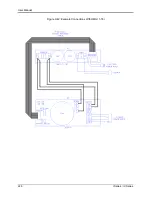
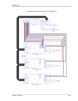
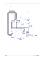
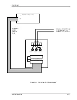
Page 240: ...User Manual 226 i Series iX Series Figure 9 42 Example Connections With OMNI 1 18i...
Page 241: ...User Manual i Series iX Series 227 Figure 9 43 Example Connections With OMNI 3 18i...

