


User Manual
94
i Series / iX Series
4.7 Transient Programming
4.7.1 Introduction
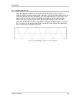
Transient programming provides a precise timing control over output voltage and frequency
changes. This mode of operation can be used to test a product for susceptibility to common AC
line conditions such as surges, sags, brownouts and spikes. By combining transient
programming with custom waveforms [
iX Series only
], virtually any AC condition can be
simulated on the output of the AC source.
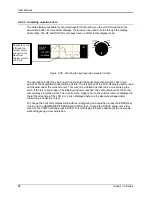
The default voltage mode is FIXED which means the output voltage is constant and remains at
the level set by the user. Changes made to the output voltage made from the PROGRAM 1
menu take effect immediately. In front panel operation mode, the voltage and frequency slew
rates (rate of change) are always at their maximum of 1E9 V/s and 1E9 Hz/s. Slew rate
programming is only possible over the IEEE-488 or RS232C bus. On power up, the AC source
always reverts to the maximum slew rate for both voltage and frequency.
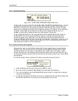
4.7.2 Using Transient Modes
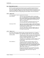
The voltage can be programmed in the following transient operating modes:
STEP
causes the output to permanently change to its triggered value.
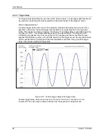
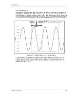
PULSE
causes the output to change to its triggered value for a specific time, as
determined by the Pulse menu parameters.
LIST
causes the output to sequence through a number of values, as determined by
points entered in the List menu.
FIXED
disables transient operation for the selected function.
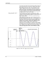
4.7.3 Step Transients
Step transients let you specify an alternate or triggered voltage level that the AC source will apply
to the output when it receives a trigger. Because the default transient voltage level is zero volts,
you must first enter a triggered voltage before you can trigger the AC source to change the
output amplitude. Step transients can only be programmed through the bus, not the front panel.
Refer to the SCPI Programming Manual for more information about programming Step transients
and triggers.
Summary of Contents for 10001i
Page 2: ......
Page 3: ......
Page 6: ...ii This page intentionally left blank...
Page 38: ...User Manual 24 i Series iX Series Figure 3 5 Rear Panel View for the 3001i 3001iX...
Page 39: ...User Manual i Series iX Series 25 Figure 3 6 Rear Panel View for the 5001i 5001iX...
Page 43: ...User Manual i Series iX Series 29 Figure 3 8 Functional Test Setup...
Page 44: ...User Manual 30 i Series iX Series Figure 3 9 Single Phase 10000 VA System 10001iX i...
Page 46: ...User Manual 32 i Series iX Series Figure 3 11 Single Phase 15000 VA System 15001iX i...
Page 48: ...User Manual 34 i Series iX Series Figure 3 13 Connection With MODE Option...
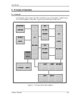
Page 118: ...User Manual 104 i Series iX Series Figure 5 2 Power Source Module Block Diagram...
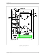
Page 121: ...User Manual i Series iX Series 107 Figure 5 3 5001i Internal Layout...
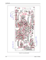
Page 122: ...User Manual 108 i Series iX Series Figure 5 4 Logic Board LED s...
Page 124: ...User Manual 110 i Series iX Series Figure 5 5 AC Power Stage Layout...
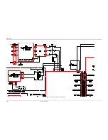
Page 125: ...User Manual i Series iX Series 111 Figure 5 6 AC Control Logic Block Diagram...
Page 138: ...User Manual 124 i Series iX Series Figure 6 3 Adjustment Location...
Page 152: ...User Manual 138 i Series iX Series Figure 9 4 Voltage Modulation...
Page 219: ...User Manual i Series iX Series 205 Figure 9 36 Example Connection With 5001iX and EOS 1...
Page 221: ...User Manual i Series iX Series 207 Figure 9 38 15003iX CTS EOS3 LR3...
Page 222: ...User Manual 208 i Series iX Series Figure 9 39 15003iX 3 EOS3...
Page 233: ...User Manual i Series iX Series 219 Figure 9 41 Example Connection With MODE iX...
Page 240: ...User Manual 226 i Series iX Series Figure 9 42 Example Connections With OMNI 1 18i...
Page 241: ...User Manual i Series iX Series 227 Figure 9 43 Example Connections With OMNI 3 18i...