

User Manual
130
i Series / iX Series
7.4.6 Disassembly Procedure
Disconnect mains power to the source and
wait 10 minutes to allow the capacitors to
discharge before attempting to disassemble the unit.
Remove the top cover, unplug P7 from
the current limit board, and unplug the fan from the AC logic board connector. Then carefully
unplug the AC logic board from the AC and the DC power boards. The AC logic board can then
be lifted from the unit.
Using a 5/16 inch socket driver remove the four bolts that hold the AC power module heatsink.
There is one bolt at each corner. Carefully remove all the hardware from the unit. The AC power
module can now be unplugged from the input/output board and removed from the unit.
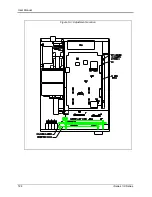
The DC - DC module can be unplugged by first removing the two nuts holding the clamp that
secures the heatsink to the chassis. See Figure 6-1. Care must be taken in unplugging the two
connectors P4 and J12.
To reassemble, reverse the above procedure, taking care to ensure J12 on the DC-DC board
and J8 on the AC board are properly mated. This may entail supporting the connector from
behind with a screwdriver.
Summary of Contents for 10001i
Page 2: ......
Page 3: ......
Page 6: ...ii This page intentionally left blank...
Page 38: ...User Manual 24 i Series iX Series Figure 3 5 Rear Panel View for the 3001i 3001iX...
Page 39: ...User Manual i Series iX Series 25 Figure 3 6 Rear Panel View for the 5001i 5001iX...
Page 43: ...User Manual i Series iX Series 29 Figure 3 8 Functional Test Setup...
Page 44: ...User Manual 30 i Series iX Series Figure 3 9 Single Phase 10000 VA System 10001iX i...
Page 46: ...User Manual 32 i Series iX Series Figure 3 11 Single Phase 15000 VA System 15001iX i...
Page 48: ...User Manual 34 i Series iX Series Figure 3 13 Connection With MODE Option...
Page 118: ...User Manual 104 i Series iX Series Figure 5 2 Power Source Module Block Diagram...
Page 121: ...User Manual i Series iX Series 107 Figure 5 3 5001i Internal Layout...
Page 122: ...User Manual 108 i Series iX Series Figure 5 4 Logic Board LED s...
Page 124: ...User Manual 110 i Series iX Series Figure 5 5 AC Power Stage Layout...
Page 125: ...User Manual i Series iX Series 111 Figure 5 6 AC Control Logic Block Diagram...
Page 138: ...User Manual 124 i Series iX Series Figure 6 3 Adjustment Location...
Page 152: ...User Manual 138 i Series iX Series Figure 9 4 Voltage Modulation...
Page 219: ...User Manual i Series iX Series 205 Figure 9 36 Example Connection With 5001iX and EOS 1...
Page 221: ...User Manual i Series iX Series 207 Figure 9 38 15003iX CTS EOS3 LR3...
Page 222: ...User Manual 208 i Series iX Series Figure 9 39 15003iX 3 EOS3...
Page 233: ...User Manual i Series iX Series 219 Figure 9 41 Example Connection With MODE iX...
Page 240: ...User Manual 226 i Series iX Series Figure 9 42 Example Connections With OMNI 1 18i...
Page 241: ...User Manual i Series iX Series 227 Figure 9 43 Example Connections With OMNI 3 18i...