


User Manual
i Series / iX Series
199
9.4 EOS Option
9.4.1 Introduction
This section contains information on the installation and operation of the EOS-1 and EOS-3
electronic output switches to be used with the California Instruments i/iX-series of power
sources.
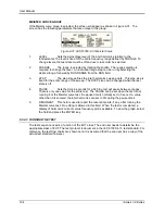
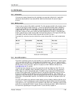
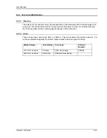
9.4.2 EOS Revisions
There are two versions of the EOS1 and EOS3. The first generation EOS1 is the original version
and has top assembly number 5100-407-1. The second generation EOS1 adds an additional
output tap at the 80% test level selectable through a front panel switch and has top assembly
number 5100-410-1, Rev A. For the EOS3, the top assembly number remains the same at
5100-407-3. However, the revision of the second generation EOS-3 is Rev E. First generation
EOS-3 units will have an older revision letter. The selection between a 70% tap and an 80% tap
on the EOS-3 must be hard wired which requires removal of the top cover.
Top assembly number and revision information can be obtained from the model number/serial
tag.
Model
Generation
Assembly
Revision
EOS1
1
5100-407-1
D or lower
2
5100-410-1
A
EOS3
1
5100-407-3
D or lower
2
5100-407-3
E
Table 9-21: EOS Versions
9.4.3 General Description
The EOS-1 and EOS-3 electronic output switches are used with the IEC1000-4-11 option (option
–411) to perform IEC1000-4-11 voltage dips and interruptions tests. The –411 option must be
installed in the iX/I power source for the EOS to function. It is configured if the EOS was ordered
with the iX/i AC source. If the-411 option is not present, contact California Instruments at
for support.
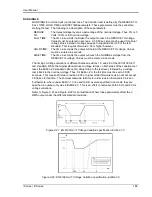
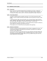
The tests are fully compliant as long as the equipment under test draws less than 70% of the
peak current drive capability of the controlling power source. The EOS-1 may be used with a
5001iX power source for single-phase tests. The EOS-3 may be used with a 15003iX power
system for three phase tests. During IEC1000-4-11 testing the EOS directs power from the iX
source to a multi-tap power transformer and a set of electronic switches. The switches are
opened and closed as required to select the appropriate tap from the transformer to send to the
EOS output. During standard operation, the transformer and switches are bypassed within the
EOS unit.
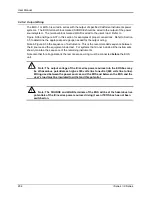
All control of the EOS unit is performed automatically by the controlling California Instruments iX
power source. The controlling power source automatically detects whether an EOS is operating
in the system or not. If the EOS unit is not powered on and active, the controlling source will still
perform non-compliant IEC1000-4-11 tests. No user controls are provided. Refer to Section 9.2
for instructions regarding performing IEC1000-4-11 tests with this equipment.
Summary of Contents for 10001i
Page 2: ......
Page 3: ......
Page 6: ...ii This page intentionally left blank...
Page 38: ...User Manual 24 i Series iX Series Figure 3 5 Rear Panel View for the 3001i 3001iX...
Page 39: ...User Manual i Series iX Series 25 Figure 3 6 Rear Panel View for the 5001i 5001iX...
Page 43: ...User Manual i Series iX Series 29 Figure 3 8 Functional Test Setup...
Page 44: ...User Manual 30 i Series iX Series Figure 3 9 Single Phase 10000 VA System 10001iX i...
Page 46: ...User Manual 32 i Series iX Series Figure 3 11 Single Phase 15000 VA System 15001iX i...
Page 48: ...User Manual 34 i Series iX Series Figure 3 13 Connection With MODE Option...
Page 118: ...User Manual 104 i Series iX Series Figure 5 2 Power Source Module Block Diagram...
Page 121: ...User Manual i Series iX Series 107 Figure 5 3 5001i Internal Layout...
Page 122: ...User Manual 108 i Series iX Series Figure 5 4 Logic Board LED s...
Page 124: ...User Manual 110 i Series iX Series Figure 5 5 AC Power Stage Layout...
Page 125: ...User Manual i Series iX Series 111 Figure 5 6 AC Control Logic Block Diagram...
Page 138: ...User Manual 124 i Series iX Series Figure 6 3 Adjustment Location...
Page 152: ...User Manual 138 i Series iX Series Figure 9 4 Voltage Modulation...
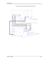
Page 219: ...User Manual i Series iX Series 205 Figure 9 36 Example Connection With 5001iX and EOS 1...
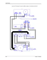
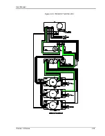
Page 221: ...User Manual i Series iX Series 207 Figure 9 38 15003iX CTS EOS3 LR3...
Page 222: ...User Manual 208 i Series iX Series Figure 9 39 15003iX 3 EOS3...
Page 233: ...User Manual i Series iX Series 219 Figure 9 41 Example Connection With MODE iX...
Page 240: ...User Manual 226 i Series iX Series Figure 9 42 Example Connections With OMNI 1 18i...
Page 241: ...User Manual i Series iX Series 227 Figure 9 43 Example Connections With OMNI 3 18i...