


User Manual
i Series / iX Series
79
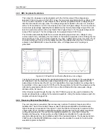
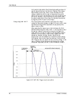
The square wave provides a high frequency content waveform with relative fast rise and fall
times. Due to AC amplifier bandwidth limitations, the frequency content of the standard square
wave has been kept within the amplifier‟s capabilities. As the fundamental frequency is
increased, the relative contribution of higher harmonics is reduced.
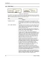
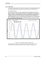
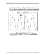
The clipped sinewave may be used to simulate voltage distortion levels to the unit under test.
The total harmonic distortion level may be programmed in percent using the CLIP LEVEL field of
the WAVEFORMS menu. Changing the distortion level of the CLIP waveform forces the AC
source to rege
nerate the CLIPPED sinewave‟s datapoints and reload the waveform register with
the newly requested data. This process requires the output to be dropped briefly. To avoid
interrupting the voltage output to the unit under test, select a different waveform such as the
standard sinewave first, change the clip level and change the waveform back to the CLIPPED
sinewave. This will avoid any output interruption.
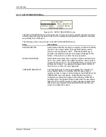
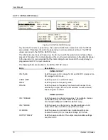
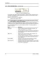
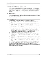
4.4.2 Phase Selection
Figure 4-29: Selecting waveforms for single phase or all phases
If the 9003iX or15003iX, different waveforms may be selected for each phase. The number of
custom waveforms from which to select remains 50 but each phase can be assigned a different
custom or standard waveform. The specific output phase for which the waveshape is
programmed is selected with the PHASE key on the front panel. The selected phase is always
shown in the top right hand corner of the WAVEFORMS display.
To select the same wave shape for all three phases in a three phase configuration, press the
PHASE key until the øABC annunciator appears in the top right corner of the WAVEFORMS
menu. Waveform selections made in this mode will apply to all three phases.
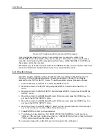
4.4.3 Creating Custom Waveforms
The iX Series provides four groups of 50 custom defined waveforms each for a total of 200
waveforms in addition to the 3 standard waveforms. Of these four groups, one may be active at a
time. The active group is selected in the INITIAL SETUP menu.
Custom waveforms cannot be created from the front panel of the iX Series. Rather, they have to
be downloaded through the IEEE-488 or RS232C interface. A Windows based program is
included with the iX Series that allows waveforms to be created and downloaded easily. This
Graphical User Interface program allows waveforms to be created by specifying harmonic
amplitudes and phase angles with respect to the fundamental. It also offers an arbitrary
waveform data entry mode that allows individual data points to be specified.
Summary of Contents for 10001i
Page 2: ......
Page 3: ......
Page 6: ...ii This page intentionally left blank...
Page 38: ...User Manual 24 i Series iX Series Figure 3 5 Rear Panel View for the 3001i 3001iX...
Page 39: ...User Manual i Series iX Series 25 Figure 3 6 Rear Panel View for the 5001i 5001iX...
Page 43: ...User Manual i Series iX Series 29 Figure 3 8 Functional Test Setup...
Page 44: ...User Manual 30 i Series iX Series Figure 3 9 Single Phase 10000 VA System 10001iX i...
Page 46: ...User Manual 32 i Series iX Series Figure 3 11 Single Phase 15000 VA System 15001iX i...
Page 48: ...User Manual 34 i Series iX Series Figure 3 13 Connection With MODE Option...
Page 118: ...User Manual 104 i Series iX Series Figure 5 2 Power Source Module Block Diagram...
Page 121: ...User Manual i Series iX Series 107 Figure 5 3 5001i Internal Layout...
Page 122: ...User Manual 108 i Series iX Series Figure 5 4 Logic Board LED s...
Page 124: ...User Manual 110 i Series iX Series Figure 5 5 AC Power Stage Layout...
Page 125: ...User Manual i Series iX Series 111 Figure 5 6 AC Control Logic Block Diagram...
Page 138: ...User Manual 124 i Series iX Series Figure 6 3 Adjustment Location...
Page 152: ...User Manual 138 i Series iX Series Figure 9 4 Voltage Modulation...
Page 219: ...User Manual i Series iX Series 205 Figure 9 36 Example Connection With 5001iX and EOS 1...
Page 221: ...User Manual i Series iX Series 207 Figure 9 38 15003iX CTS EOS3 LR3...
Page 222: ...User Manual 208 i Series iX Series Figure 9 39 15003iX 3 EOS3...
Page 233: ...User Manual i Series iX Series 219 Figure 9 41 Example Connection With MODE iX...
Page 240: ...User Manual 226 i Series iX Series Figure 9 42 Example Connections With OMNI 1 18i...
Page 241: ...User Manual i Series iX Series 227 Figure 9 43 Example Connections With OMNI 3 18i...