


User Manual
i Series / iX Series
97
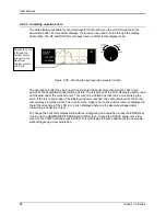
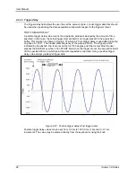
8. The START ø may be left at RANDOM as we are not interested in starting at a specific
phase angle. If a number is already present in this field, use the BACKSPACE (<-) key to
clear it.
9. Move the cursor to the GO TO VOLT field and enter 160.0
10. Move the cursor to the DUR SCALE field and set this field to TIME. We will be entering
delays in time rather than cycles since this example was stated in ms.
11. Move the cursor to the DURATION field and enter 0.033 seconds. Be sure not to enter 33 as
this field is specified in seconds, not milliseconds. The highest time resolution available for
list transients is 1 ms or 0.001 s.
12. Move to the END VOLT field and enter 0.0. We want the voltage to return to 0 Volt after the
first burst.
13. Move the cursor to the END DELAY field and enter 0.067 for a interval delay of 67 ms.
Notice that we effectively combined steps 0 and 1 from Figure 4-40 into a single list event.
14. If you have an iX Series AC source, move down to the FUNCTION field and use the knob to
select SINE. The knob will allow you to scroll through all available waveshapes in the active
WAVE GROUP. If you have an i Series AC Source, this field will not be visible.
15. Move the cursor to the REPEAT field and enter 0. This means this event will be executed
once and not repeated. Do not confuse this event level repeat capability with the entire list
level repeat field which we will use later.
16. Move the cursor down to the EVENT # field and enter a number from 1 through 99. The
transient list will be executed in order of event number. Leaving a gap between event
numbers allows you to insert events at different places later in the sequence. Deleting
events is always possible regardless of the event number. For the purpose of this exercise,
we will start with EVENT # 5. Enter 5 and press the ENTER key. This brings you back to the
TRANSIENTS menu.
17. Repeat steps 6 through 16 two more times using 120 V, 83 ms and 80 V, 150 ms as values
for EVENT # 10 and EVENT #15.
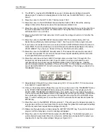
18. Once you have programmed these three events, move the cursor in the TRANSIENTS menu
to the START/VIEW SEQUENCE field and press the ENTER key. This will get you to the
START/VIEW TRANSIENT SEQUENCE menu from which you can run transient programs.
This screen shows all available events in the transient list on the right hand side. If more than
five events are programmed, you can scroll through the list using the UP and DOWN arrow
keys. To edit an existing event, move the cursor to the relevant event number and press the
ENTER key.
19. Move the cursor to the REPEAT #0 field and enter 1. This will cause the transient program to
repeat once and thus run two times total. Do not confuse this global list level repeat capability
with the list event level repeat field we skipped in step 15.
20. Make sure the output relay is closed using the OUTPUT ON/OFF key. If you start a transient
program with the relay open, an error message will appear.
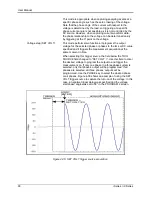
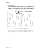
21. Move the cursor to the START field and press the ENTER key. The transient program you
just created will execute two times. If you have an oscilloscope connected to the output, you
may be able to see the output voltage change per Figure 4-40.
Summary of Contents for 10001i
Page 2: ......
Page 3: ......
Page 6: ...ii This page intentionally left blank...
Page 38: ...User Manual 24 i Series iX Series Figure 3 5 Rear Panel View for the 3001i 3001iX...
Page 39: ...User Manual i Series iX Series 25 Figure 3 6 Rear Panel View for the 5001i 5001iX...
Page 43: ...User Manual i Series iX Series 29 Figure 3 8 Functional Test Setup...
Page 44: ...User Manual 30 i Series iX Series Figure 3 9 Single Phase 10000 VA System 10001iX i...
Page 46: ...User Manual 32 i Series iX Series Figure 3 11 Single Phase 15000 VA System 15001iX i...
Page 48: ...User Manual 34 i Series iX Series Figure 3 13 Connection With MODE Option...
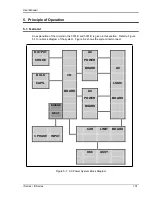
Page 118: ...User Manual 104 i Series iX Series Figure 5 2 Power Source Module Block Diagram...
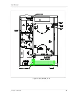
Page 121: ...User Manual i Series iX Series 107 Figure 5 3 5001i Internal Layout...
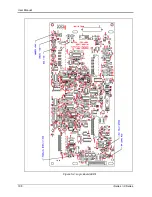
Page 122: ...User Manual 108 i Series iX Series Figure 5 4 Logic Board LED s...
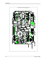
Page 124: ...User Manual 110 i Series iX Series Figure 5 5 AC Power Stage Layout...
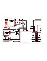
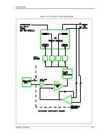
Page 125: ...User Manual i Series iX Series 111 Figure 5 6 AC Control Logic Block Diagram...
Page 138: ...User Manual 124 i Series iX Series Figure 6 3 Adjustment Location...
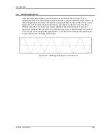
Page 152: ...User Manual 138 i Series iX Series Figure 9 4 Voltage Modulation...
Page 219: ...User Manual i Series iX Series 205 Figure 9 36 Example Connection With 5001iX and EOS 1...
Page 221: ...User Manual i Series iX Series 207 Figure 9 38 15003iX CTS EOS3 LR3...
Page 222: ...User Manual 208 i Series iX Series Figure 9 39 15003iX 3 EOS3...
Page 233: ...User Manual i Series iX Series 219 Figure 9 41 Example Connection With MODE iX...
Page 240: ...User Manual 226 i Series iX Series Figure 9 42 Example Connections With OMNI 1 18i...
Page 241: ...User Manual i Series iX Series 227 Figure 9 43 Example Connections With OMNI 3 18i...