User Manual
i Series / iX Series
241
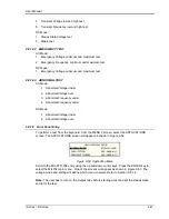
7. Transient Voltage low and high test
8. Transient Frequency low and high test
DC Mode:
1. Steady State Voltage test
2. Ripple test
9.8.1.4.2 EMERGENCY TEST
AC Mode:
1. Emergency Voltage minimum and maximum test
2. Emergency Frequency minimum and maximum test
DC Mode:
1. Emergency Voltage minimum and maximum test
9.8.1.4.3 ABNORMAL TEST
AC Mode:
1. Abnormal Voltage under
2. Abnormal Voltage over
3. Abnormal Frequency under
4. Abnormal Frequency under
DC Mode:
1. Abnormal Voltage under
2. Abnormal Voltage over
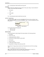
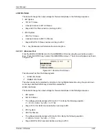
9.8.1.5 Front Panel Entry
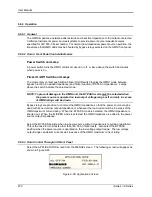
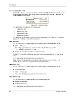
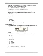
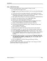
To perform a test from the keyboard, from the MENU 2 screen, select the APPLICATIONS
screen. The APPLICATIONS screen will appear as shown in Figure 9-52.
Figure 9-52: Application Menu
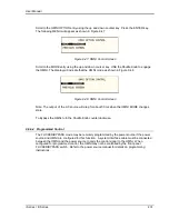
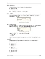
Scroll to the MIL-STD-704 entry using the up and down cursor keys. Press the ENTER key to
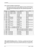
select the MIL704 main menu. One of the screens will appear as shown in Figure 9-53. The
voltage mode and setting will define which menu to select. Refer to Section 9.8.1.2
Note:
The user has to turn on the Output relay before starting a test and set the steady state
setup for the test.
Summary of Contents for 10001i
Page 2: ......
Page 3: ......
Page 6: ...ii This page intentionally left blank...
Page 38: ...User Manual 24 i Series iX Series Figure 3 5 Rear Panel View for the 3001i 3001iX...
Page 39: ...User Manual i Series iX Series 25 Figure 3 6 Rear Panel View for the 5001i 5001iX...
Page 43: ...User Manual i Series iX Series 29 Figure 3 8 Functional Test Setup...
Page 44: ...User Manual 30 i Series iX Series Figure 3 9 Single Phase 10000 VA System 10001iX i...
Page 46: ...User Manual 32 i Series iX Series Figure 3 11 Single Phase 15000 VA System 15001iX i...
Page 48: ...User Manual 34 i Series iX Series Figure 3 13 Connection With MODE Option...
Page 118: ...User Manual 104 i Series iX Series Figure 5 2 Power Source Module Block Diagram...
Page 121: ...User Manual i Series iX Series 107 Figure 5 3 5001i Internal Layout...
Page 122: ...User Manual 108 i Series iX Series Figure 5 4 Logic Board LED s...
Page 124: ...User Manual 110 i Series iX Series Figure 5 5 AC Power Stage Layout...
Page 125: ...User Manual i Series iX Series 111 Figure 5 6 AC Control Logic Block Diagram...
Page 138: ...User Manual 124 i Series iX Series Figure 6 3 Adjustment Location...
Page 152: ...User Manual 138 i Series iX Series Figure 9 4 Voltage Modulation...
Page 219: ...User Manual i Series iX Series 205 Figure 9 36 Example Connection With 5001iX and EOS 1...
Page 221: ...User Manual i Series iX Series 207 Figure 9 38 15003iX CTS EOS3 LR3...
Page 222: ...User Manual 208 i Series iX Series Figure 9 39 15003iX 3 EOS3...
Page 233: ...User Manual i Series iX Series 219 Figure 9 41 Example Connection With MODE iX...
Page 240: ...User Manual 226 i Series iX Series Figure 9 42 Example Connections With OMNI 1 18i...
Page 241: ...User Manual i Series iX Series 227 Figure 9 43 Example Connections With OMNI 3 18i...

