


User Manual
80
i Series / iX Series
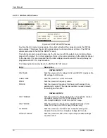
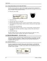
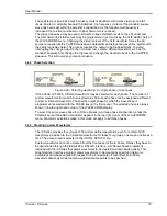
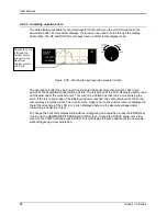
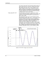
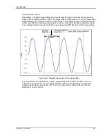
Figure 4-30: Custom waveform creation with GUI program
Once downloaded, waveforms remain in non-volatile memory and will be visible in the
WAVEFORMS menu for selection. The user can assign a 12-character name to each custom
waveform. Avoid using any of the standard waveform names (SINE, SQUARE or CLIPPED) as
these names will not be accepted.
Waveforms may be deleted using the IEEE-488 or RS232C interface as well. Custom waveforms
cannot be deleted from the front panel however to avoid accidental erasure.
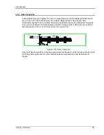
4.4.4 Waveform Groups
Waveform groups extend the number of available custom waveform to 200. Each group can
contain up to 50 user defined waveforms. Groups are numbered 0 through 3 and may be
selected from the INITIAL SETUP 3 menu. To switch waveform groups, proceed as follows:
1. Press the MENU key three times to select the MENU 3 screen.
2. Move the cursor to the UTILITY entry end press ENTER. You are now in the UTILITY 1
menu.
3. Move the cursor to the INITIAL SETUP field and press ENTER. You are now in the INITIAL
SETUP 1 menu.
4. Move the cursor to the MORE field at the end of this menu and press the ENTER key. You
are now in the INITIAL SETUP 2 menu.
5. Move the cursor to the MORE field at the end of this menu and press the ENTER key. You
are now in the INITIAL SETUP 3 menu.
6. Move the cursor to the WAVE GROUP = field. You can now use the knob or the 0 through 3
key on the front panel to select a different waveform group.
7. Press ENTER to confirm your new selection.
8. To activate your new selection, YOU MUST CYCLE THE POWER so the AC source re-
initializes. If the source is operated over the bus, a IEEE-488 Device Clear or reset command
(*RST) command will have the same effect.
The new wave group will be active after you turn the power to the unit back on.
Summary of Contents for 10001i
Page 2: ......
Page 3: ......
Page 6: ...ii This page intentionally left blank...
Page 38: ...User Manual 24 i Series iX Series Figure 3 5 Rear Panel View for the 3001i 3001iX...
Page 39: ...User Manual i Series iX Series 25 Figure 3 6 Rear Panel View for the 5001i 5001iX...
Page 43: ...User Manual i Series iX Series 29 Figure 3 8 Functional Test Setup...
Page 44: ...User Manual 30 i Series iX Series Figure 3 9 Single Phase 10000 VA System 10001iX i...
Page 46: ...User Manual 32 i Series iX Series Figure 3 11 Single Phase 15000 VA System 15001iX i...
Page 48: ...User Manual 34 i Series iX Series Figure 3 13 Connection With MODE Option...
Page 118: ...User Manual 104 i Series iX Series Figure 5 2 Power Source Module Block Diagram...
Page 121: ...User Manual i Series iX Series 107 Figure 5 3 5001i Internal Layout...
Page 122: ...User Manual 108 i Series iX Series Figure 5 4 Logic Board LED s...
Page 124: ...User Manual 110 i Series iX Series Figure 5 5 AC Power Stage Layout...
Page 125: ...User Manual i Series iX Series 111 Figure 5 6 AC Control Logic Block Diagram...
Page 138: ...User Manual 124 i Series iX Series Figure 6 3 Adjustment Location...
Page 152: ...User Manual 138 i Series iX Series Figure 9 4 Voltage Modulation...
Page 219: ...User Manual i Series iX Series 205 Figure 9 36 Example Connection With 5001iX and EOS 1...
Page 221: ...User Manual i Series iX Series 207 Figure 9 38 15003iX CTS EOS3 LR3...
Page 222: ...User Manual 208 i Series iX Series Figure 9 39 15003iX 3 EOS3...
Page 233: ...User Manual i Series iX Series 219 Figure 9 41 Example Connection With MODE iX...
Page 240: ...User Manual 226 i Series iX Series Figure 9 42 Example Connections With OMNI 1 18i...
Page 241: ...User Manual i Series iX Series 227 Figure 9 43 Example Connections With OMNI 3 18i...