


User Manual
i Series / iX Series
85
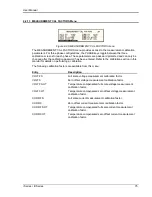
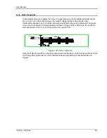
4.6 Advanced Measurements [
iX Series only
]
The iX Series offers advanced power analyzer measurement capabilities. These functions may
be accessed from the MEAS button or the MENU 2 screen. The phase for which the analysis or
waveform acquisition is done may be selected using the PHASE key in three phase
configurations. This chapter covers the use and application of these advanced measurement
functions.
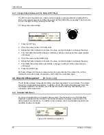
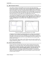
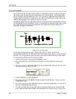
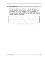
4.6.1 Harmonic Analysis
The iX power analyzer performs fast fourrier transformation on both voltage and current on each
available phase. The resulting frequency spectrum can be displayed on the LCD display in a
tabular as well as a graphical mode.
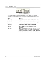
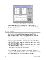
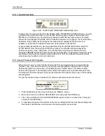
4.6.1.1 Acquiring FFT data
To perform an FFT analysis on the output of the AC source, proceed as follows:
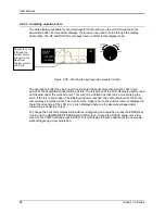
1. Press the MEAS button four times or until the HARMONICS/TRACE ANALYSIS screen
appears.
2. Move the cursor to the FUNCTION field and select VOLT or CURR. (The BOTH selection
will default to CURR as only one FFT result can be displayed at a time.)
3. Move the cursor to the VIEW field and select the TABLE or BAR display mode. The TRACE
display mode does not apply to FFT results.
4. Move the cursor to the DATA MODE field and select ABS or REL. Absolute display mode will
show all harmonic components in volts or amps. Relative display mode will use the
fundamental as a 100 % reference and display all harmonics as a percentage of the
fundamental. Phase angles are always shown with respect to the fundamental frequency.
The phase angle of the fundamental is always shown with respect to phase A.
5. Skip the SCALE field as it only applies to the TRACE display mode.
6. Move the cursor to the TRIG MODE and select SINGLE or CONT. The SINGLE mode will
acquire the data once and show the result. If you select CONT, the data will be updated
continuously.
7. Move the cursor to the TRIG SOURCE field and select IMM. We will cover additional trigger
modes later.
8. Move the cursor to the START field and press the ENTER key. The display that you selected
will be shown. If you are in CONT trigger mode, the data will be updated about once per
second.
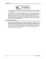
You can return to the HARMONICS/TRACE ANALYSIS screen by pressing the ENTER key. To
display the data in a different format, change to the selections you want and move the cursor to
the VIEW field. Pressing the ENTER key will re-display the data without triggering a new
acquisition. (This is true even if you were in CONT trigger mode.) To start a new acquisition, you
must go through the START field instead.
Summary of Contents for 10001i
Page 2: ......
Page 3: ......
Page 6: ...ii This page intentionally left blank...
Page 38: ...User Manual 24 i Series iX Series Figure 3 5 Rear Panel View for the 3001i 3001iX...
Page 39: ...User Manual i Series iX Series 25 Figure 3 6 Rear Panel View for the 5001i 5001iX...
Page 43: ...User Manual i Series iX Series 29 Figure 3 8 Functional Test Setup...
Page 44: ...User Manual 30 i Series iX Series Figure 3 9 Single Phase 10000 VA System 10001iX i...
Page 46: ...User Manual 32 i Series iX Series Figure 3 11 Single Phase 15000 VA System 15001iX i...
Page 48: ...User Manual 34 i Series iX Series Figure 3 13 Connection With MODE Option...
Page 118: ...User Manual 104 i Series iX Series Figure 5 2 Power Source Module Block Diagram...
Page 121: ...User Manual i Series iX Series 107 Figure 5 3 5001i Internal Layout...
Page 122: ...User Manual 108 i Series iX Series Figure 5 4 Logic Board LED s...
Page 124: ...User Manual 110 i Series iX Series Figure 5 5 AC Power Stage Layout...
Page 125: ...User Manual i Series iX Series 111 Figure 5 6 AC Control Logic Block Diagram...
Page 138: ...User Manual 124 i Series iX Series Figure 6 3 Adjustment Location...
Page 152: ...User Manual 138 i Series iX Series Figure 9 4 Voltage Modulation...
Page 219: ...User Manual i Series iX Series 205 Figure 9 36 Example Connection With 5001iX and EOS 1...
Page 221: ...User Manual i Series iX Series 207 Figure 9 38 15003iX CTS EOS3 LR3...
Page 222: ...User Manual 208 i Series iX Series Figure 9 39 15003iX 3 EOS3...
Page 233: ...User Manual i Series iX Series 219 Figure 9 41 Example Connection With MODE iX...
Page 240: ...User Manual 226 i Series iX Series Figure 9 42 Example Connections With OMNI 1 18i...
Page 241: ...User Manual i Series iX Series 227 Figure 9 43 Example Connections With OMNI 3 18i...