


User Manual
62
i Series / iX Series
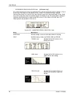
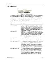
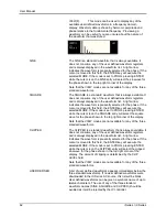
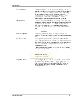
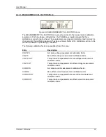
VIEW(F):
This mode can be used to display any of the
available user defined waveforms in a frequency domain
display. Waveform data is shown by harmonic amplitude and
phase relative to the fundamental frequency. Previewing a
waveform can be useful if you are unsure about the nature of
the waveform that was stored.
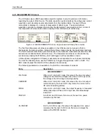
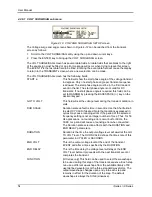
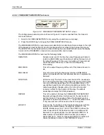
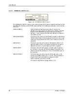
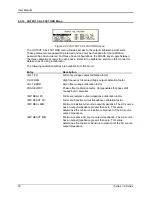
SINE
The SINE is a standard waveform that is always available. It
does not consume any of the user defined waveform registers
and is always displayed in the waveform list. A right arrow
indicates the waveform is presently selected for the phase. If the
cursor is moved to this field, the ENTER key will execute the
selected MODE. If the mode is set to PROG, pressing ENTER
while the cursor is on the SINE entry will select the sinewave for
the phase shown in the top right corner of the display.
Note that the VIEW modes are not available for any of the three
standard waveforms.
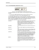
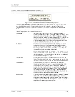
SQUARE
The SQUARE is a standard waveform that is always available. It
does not consume any of the user defined waveform registers
and is always displayed in the waveform list. A right arrow
indicates the waveform is presently selected for the phase. If the
cursor is moved to this field, the ENTER key will execute the
selected MODE. If the mode is set to PROG, pressing ENTER
while the cursor is on the SQUARE entry will select the square
wave for the phase shown in the top right corner of the display.
Note that the VIEW modes are not available for any of the three
standard waveforms.
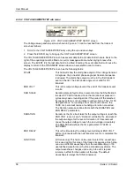
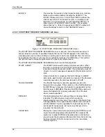
CLIPPED
The CLIPPED is a standard waveform that is always available. It
does not consume any of the user defined waveform registers
and is always displayed in the waveform list. A right arrow
indicates the waveform is presently selected for the phase. If the
cursor is moved to this field, the ENTER key will execute the
selected MODE. If the mode is set to PROG, pressing ENTER
while the cursor is on the CLIPPED entry will select the clipped
sinewave for the phase shown in the top right corner of the
display. The amount of clipping is determined by the CLIP
LEVEL field.
Note that the VIEW modes are not available for any of the three
standard waveforms.
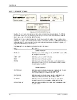
USER DEFINED
A list of user defined waveforms appears immediately below the
three standard waveforms. If no user defined waveforms were
downloaded to the iX Series AC source, this list will be blank.
User defined waveforms can be given a symbolic name of up to
twelve characters. The use of any of the three standard
waveform names (SINE, SQUARE and CLIPPED) should be
avoided as it will be rejected by the iX controller.
Summary of Contents for 10001i
Page 2: ......
Page 3: ......
Page 6: ...ii This page intentionally left blank...
Page 38: ...User Manual 24 i Series iX Series Figure 3 5 Rear Panel View for the 3001i 3001iX...
Page 39: ...User Manual i Series iX Series 25 Figure 3 6 Rear Panel View for the 5001i 5001iX...
Page 43: ...User Manual i Series iX Series 29 Figure 3 8 Functional Test Setup...
Page 44: ...User Manual 30 i Series iX Series Figure 3 9 Single Phase 10000 VA System 10001iX i...
Page 46: ...User Manual 32 i Series iX Series Figure 3 11 Single Phase 15000 VA System 15001iX i...
Page 48: ...User Manual 34 i Series iX Series Figure 3 13 Connection With MODE Option...
Page 118: ...User Manual 104 i Series iX Series Figure 5 2 Power Source Module Block Diagram...
Page 121: ...User Manual i Series iX Series 107 Figure 5 3 5001i Internal Layout...
Page 122: ...User Manual 108 i Series iX Series Figure 5 4 Logic Board LED s...
Page 124: ...User Manual 110 i Series iX Series Figure 5 5 AC Power Stage Layout...
Page 125: ...User Manual i Series iX Series 111 Figure 5 6 AC Control Logic Block Diagram...
Page 138: ...User Manual 124 i Series iX Series Figure 6 3 Adjustment Location...
Page 152: ...User Manual 138 i Series iX Series Figure 9 4 Voltage Modulation...
Page 219: ...User Manual i Series iX Series 205 Figure 9 36 Example Connection With 5001iX and EOS 1...
Page 221: ...User Manual i Series iX Series 207 Figure 9 38 15003iX CTS EOS3 LR3...
Page 222: ...User Manual 208 i Series iX Series Figure 9 39 15003iX 3 EOS3...
Page 233: ...User Manual i Series iX Series 219 Figure 9 41 Example Connection With MODE iX...
Page 240: ...User Manual 226 i Series iX Series Figure 9 42 Example Connections With OMNI 1 18i...
Page 241: ...User Manual i Series iX Series 227 Figure 9 43 Example Connections With OMNI 3 18i...