


User Manual
194
i Series / iX Series
MEISTER CURVE GROUP
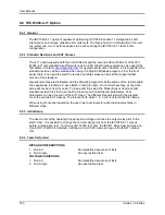
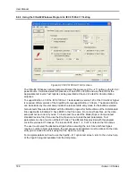
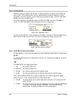
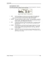
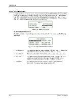
If the Meister curve group is selected, the screen will appear as shown in Figure 9-31. The
screen has the following parameters that are unique to the group:
Figure 9-31: IEC 61000-4-13 Meister Curve
1.
LEVEL
Sets the percentage level of the inter harmonics relative to the
fundamental. The level is fixed for the entire frequency range defined by FRANGE. To
change levels, the test state must be off and user class must be selected.
2.
FRANGE
The range is selected by rotating the shuttle. The range selection is
required to change the level. An individual range step can be run by selecting the
desired range, followed by RUN RANGE from the RUN field.
3.
STEP
The step size defines the inter harmonics sweep points. This step size is
fixed for the entire range of the sweep. The STEP size can be changed when the test
state is off.
4.
PAUSE
Sets the time in seconds for which the test will pause between ranges.
There is only one value for the entire test. The PAUSE can be set when the test is not
running. For the Meister curve test, the pause time is normally set to 0 secs. If a value
other than 0 is entered, the inter harmonics are set to 0% during the pause times.
5.
RESONANT
This field is used to report the resonant points, if any, after running the
Meister curve test. No editing is allowed in this field. When the test is completed, a
display of harmonics current versus frequency plot is available. To view the graph, select
the field and press the ENTER key.
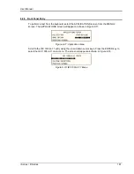
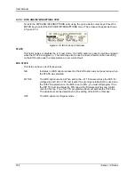
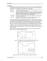
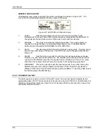
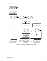
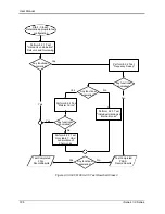
9.3.4.3 RUNNING THE TEST
The test sequence used is a function of the EUT class. The end user needs to determine the
appropriate class of EUT. The test protocol is document in the IEC 61000-4-13 test standard. For
reference, the test flow charts are shown here. It is assumed that the end user has a copy of the
actual test standard however.
Summary of Contents for 10001i
Page 2: ......
Page 3: ......
Page 6: ...ii This page intentionally left blank...
Page 38: ...User Manual 24 i Series iX Series Figure 3 5 Rear Panel View for the 3001i 3001iX...
Page 39: ...User Manual i Series iX Series 25 Figure 3 6 Rear Panel View for the 5001i 5001iX...
Page 43: ...User Manual i Series iX Series 29 Figure 3 8 Functional Test Setup...
Page 44: ...User Manual 30 i Series iX Series Figure 3 9 Single Phase 10000 VA System 10001iX i...
Page 46: ...User Manual 32 i Series iX Series Figure 3 11 Single Phase 15000 VA System 15001iX i...
Page 48: ...User Manual 34 i Series iX Series Figure 3 13 Connection With MODE Option...
Page 118: ...User Manual 104 i Series iX Series Figure 5 2 Power Source Module Block Diagram...
Page 121: ...User Manual i Series iX Series 107 Figure 5 3 5001i Internal Layout...
Page 122: ...User Manual 108 i Series iX Series Figure 5 4 Logic Board LED s...
Page 124: ...User Manual 110 i Series iX Series Figure 5 5 AC Power Stage Layout...
Page 125: ...User Manual i Series iX Series 111 Figure 5 6 AC Control Logic Block Diagram...
Page 138: ...User Manual 124 i Series iX Series Figure 6 3 Adjustment Location...
Page 152: ...User Manual 138 i Series iX Series Figure 9 4 Voltage Modulation...
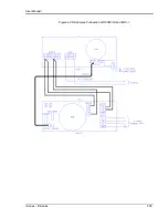
Page 219: ...User Manual i Series iX Series 205 Figure 9 36 Example Connection With 5001iX and EOS 1...
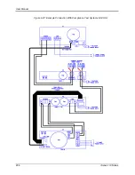
Page 221: ...User Manual i Series iX Series 207 Figure 9 38 15003iX CTS EOS3 LR3...
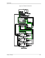
Page 222: ...User Manual 208 i Series iX Series Figure 9 39 15003iX 3 EOS3...
Page 233: ...User Manual i Series iX Series 219 Figure 9 41 Example Connection With MODE iX...
Page 240: ...User Manual 226 i Series iX Series Figure 9 42 Example Connections With OMNI 1 18i...
Page 241: ...User Manual i Series iX Series 227 Figure 9 43 Example Connections With OMNI 3 18i...