


User Manual
242
i Series / iX Series
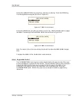
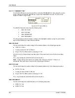
Figure 9-53: MIL704 Menu
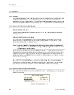
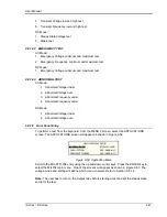
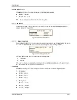
9.8.1.6 Revision Selection
The default Revision is E. Revisions supported are D and E. The Revision can be changed from
the front panel. Scroll to the REVISION entry using the up and down cursor keys (see Figure
9-53). Use the shuttle to change the selection.
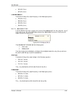
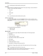
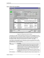
9.8.1.7 AC MODE TESTS
9.8.1.7.1 Steady StateTest
Scroll to the STEADY STATE AC entry using the up and down cursor keys. Press the ENTER
key to select the STEADY STATE screens. The screen will appear as shown in Figure 9-54.
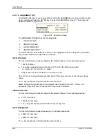
Figure 9-54: Steady State Menu
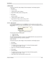
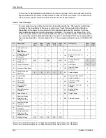
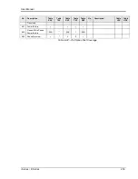
The MIL704 Steady state 1 and Steady state 2 screens have the following tests:
1
VOLTAGE
2
FREQUENCY
3
VOLT UNBALANCE
4
PHASE DIFFERENCE
5
VOLT MODULATION
6
FREQ MODULATION
7
DISTORTION
The above tests can be selected by scrolling to the highlighted selection using the up and down
cursor keys and the ENTER key to start the selected test.
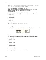
VOLTAGE
This test will change the output voltage in the following sequence:
108V for 1 minute.
118V for 1 minute.
115V for 1 minute.
The
key (backspace) will terminate the test at any time.
FREQUENCY
Summary of Contents for 10001i
Page 2: ......
Page 3: ......
Page 6: ...ii This page intentionally left blank...
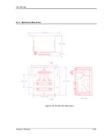
Page 38: ...User Manual 24 i Series iX Series Figure 3 5 Rear Panel View for the 3001i 3001iX...
Page 39: ...User Manual i Series iX Series 25 Figure 3 6 Rear Panel View for the 5001i 5001iX...
Page 43: ...User Manual i Series iX Series 29 Figure 3 8 Functional Test Setup...
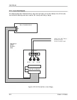
Page 44: ...User Manual 30 i Series iX Series Figure 3 9 Single Phase 10000 VA System 10001iX i...
Page 46: ...User Manual 32 i Series iX Series Figure 3 11 Single Phase 15000 VA System 15001iX i...
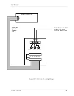
Page 48: ...User Manual 34 i Series iX Series Figure 3 13 Connection With MODE Option...
Page 118: ...User Manual 104 i Series iX Series Figure 5 2 Power Source Module Block Diagram...
Page 121: ...User Manual i Series iX Series 107 Figure 5 3 5001i Internal Layout...
Page 122: ...User Manual 108 i Series iX Series Figure 5 4 Logic Board LED s...
Page 124: ...User Manual 110 i Series iX Series Figure 5 5 AC Power Stage Layout...
Page 125: ...User Manual i Series iX Series 111 Figure 5 6 AC Control Logic Block Diagram...
Page 138: ...User Manual 124 i Series iX Series Figure 6 3 Adjustment Location...
Page 152: ...User Manual 138 i Series iX Series Figure 9 4 Voltage Modulation...
Page 219: ...User Manual i Series iX Series 205 Figure 9 36 Example Connection With 5001iX and EOS 1...
Page 221: ...User Manual i Series iX Series 207 Figure 9 38 15003iX CTS EOS3 LR3...
Page 222: ...User Manual 208 i Series iX Series Figure 9 39 15003iX 3 EOS3...
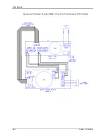
Page 233: ...User Manual i Series iX Series 219 Figure 9 41 Example Connection With MODE iX...
Page 240: ...User Manual 226 i Series iX Series Figure 9 42 Example Connections With OMNI 1 18i...
Page 241: ...User Manual i Series iX Series 227 Figure 9 43 Example Connections With OMNI 3 18i...


