


User Manual
i Series / iX Series
151
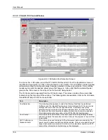
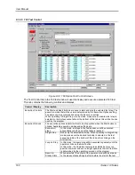
This section of the manual covers operation of the
–160 option using the CIGui32 program.
Version 1.26 or higher of the CIGui32 program is required. The CIGui32 program is supplied with
all iX systems free of charge on CD ROM CIC496. It can also be downloaded from the California
Instruments web site (
www.calinst.com
).
The information provided in this user manual is aimed at guiding the operator in the use of the
160 option through the use of the CIGui32 program. Much of the same information can be found
in the on-line help system of the CIGUI32.
This manual is
not
intended to elaborate on the intent or purpose of the immunity tests and the
expected behavior of the EUT as described in the RTCA/DO-160 documents. It is assumed that
the end-user is familiar with the content of the RTCA/DO-160 test standard.
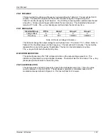
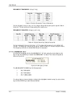
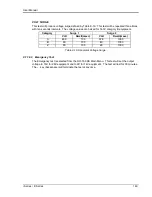
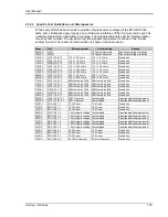
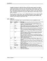
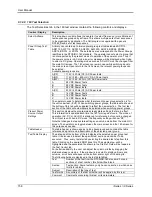
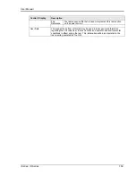
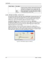
9.1.2.2 Test Coverage
The comprehensiveness of the tests that can be performed with the
–160 option is determined
primarily by the capabilities of the power source used. Tests that are outside the hardware
capabilities of the power source used will not be enabled and cannot be selected. For these
tests, additional equipment may be required as indicated. The extent of coverage of the
–160
option as implemented on the iX Series platform is shown in the table below. Tests marked with
an „x‟ generally require additional hardware to be used. Tests marked „N/A‟ are not applicable to
the corresponding table. Tests marked with a „ ‟ are covered by the –160 option. Tests marked
with a „P‟ are limited in scope and may require additional equipment to perform completely.
No.
115V Tests
Description
Table
A(CF)
Table
A(NF)
Table
A(WF)
No.
28 VDC Tests
Description
Table
ADC
Table
BDC
Table
ZDC
16.5.1.1
Voltage and
Frequency
16.6.1.1
Voltage
16.5.1.2
Voltage Modulation
16.6.1.2
Ripple Voltage
P
P
P
16.5.1.3
Frequency
Modulation
16.6.1.3
Momentary Power
Interruptions
16.5.1.4
Momentary Power
Interruptions
16.6.1.4
Normal Surge
Voltage
16.5.1.5.1
Normal Surge
Voltage
16.6.1.5
Engine Starting
Under Voltage
N/A
16.5.1.5.2
Normal Frequency
Transients
N/A
N/A
16.6.2.1
Abnormal Voltage
16.5.1.6
Normal Frequency
Variations
N/A
16.6.2.2
Low Voltage
Conditions
N/A
N/A
16.5.1.7
Voltage DC
Content
16.6.2.3
Momentary Under
Voltage Operation
16.5.1.8
Voltage Distortion
P
P
P
16.6.2.4
Abnormal Voltage
Surge
16.5.2.1
Abnormal Voltage
and Frequency
16.5.2.2
Momentary Under
Voltage Operation
16.5.2.3.1
Abnormal Surge
Voltage
16.5.2.3.2
Abnormal
Frequency
Transient
N/A
N/A
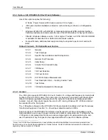
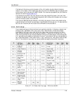
Table 9-17: -160 Option Test Coverage, 115VAC and 28VDC
Summary of Contents for 10001i
Page 2: ......
Page 3: ......
Page 6: ...ii This page intentionally left blank...
Page 38: ...User Manual 24 i Series iX Series Figure 3 5 Rear Panel View for the 3001i 3001iX...
Page 39: ...User Manual i Series iX Series 25 Figure 3 6 Rear Panel View for the 5001i 5001iX...
Page 43: ...User Manual i Series iX Series 29 Figure 3 8 Functional Test Setup...
Page 44: ...User Manual 30 i Series iX Series Figure 3 9 Single Phase 10000 VA System 10001iX i...
Page 46: ...User Manual 32 i Series iX Series Figure 3 11 Single Phase 15000 VA System 15001iX i...
Page 48: ...User Manual 34 i Series iX Series Figure 3 13 Connection With MODE Option...
Page 118: ...User Manual 104 i Series iX Series Figure 5 2 Power Source Module Block Diagram...
Page 121: ...User Manual i Series iX Series 107 Figure 5 3 5001i Internal Layout...
Page 122: ...User Manual 108 i Series iX Series Figure 5 4 Logic Board LED s...
Page 124: ...User Manual 110 i Series iX Series Figure 5 5 AC Power Stage Layout...
Page 125: ...User Manual i Series iX Series 111 Figure 5 6 AC Control Logic Block Diagram...
Page 138: ...User Manual 124 i Series iX Series Figure 6 3 Adjustment Location...
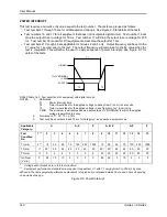
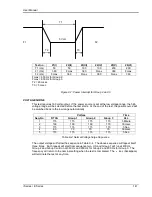
Page 152: ...User Manual 138 i Series iX Series Figure 9 4 Voltage Modulation...
Page 219: ...User Manual i Series iX Series 205 Figure 9 36 Example Connection With 5001iX and EOS 1...
Page 221: ...User Manual i Series iX Series 207 Figure 9 38 15003iX CTS EOS3 LR3...
Page 222: ...User Manual 208 i Series iX Series Figure 9 39 15003iX 3 EOS3...
Page 233: ...User Manual i Series iX Series 219 Figure 9 41 Example Connection With MODE iX...
Page 240: ...User Manual 226 i Series iX Series Figure 9 42 Example Connections With OMNI 1 18i...
Page 241: ...User Manual i Series iX Series 227 Figure 9 43 Example Connections With OMNI 3 18i...


