User Manual
66
i Series / iX Series
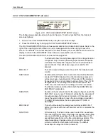
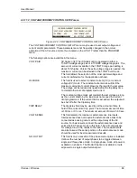
4.2.11 UTILITY Menus
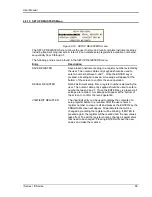
Figure 4-20: UTILITY menu
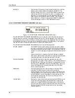
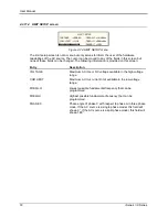
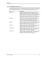
The UTILITY menu provides access to less frequently used setup items. There is no connection
between the various entries in the UTILITY menu other than there is no other logical place to put
them. The following entries can be found in the UTILITY menu:
Entry
Description
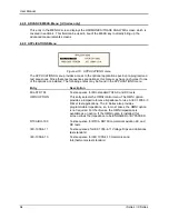
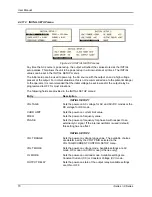
UTILITY 1
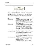
GPIB/RS232 SETUP
This entry provides access to the setup parameters for either
the IEEE-488 bus or the RS232C bus. All parameters are saved
in non-volatile memory so their is rarely a need to change these
values.
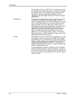
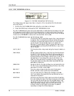
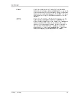
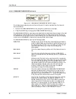
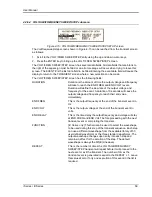
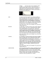
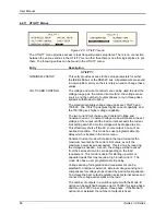
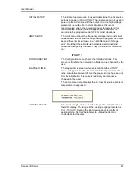
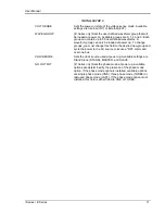
VOLT/CURR CONTROL
The voltage and current control menu can be used to select the
voltage range pair, the current limit method, the voltage sense
source, and the number of output phases (only in three phase
systems with Mode-iX option).
The standard available voltage range pairs are 135/270 and
150/300. The 135/270 pair gives higher current capability, and
the 150/300 gives higher voltage capability.
The two current limit choices are Constant Voltage and
Constant Current. Constant Voltage mode will maintain the set
voltage at the output until the load current exceeds the current
limit setting at which time the voltage will be dropped to zero.
This effectively shuts off the AC source output in case of an
overload condition. This mode has user programmable trip
delay which is located in the same menu.
Constant Current mode will maintain the load current at the
maximum level set by the current limit value, even if the
maximum power level is exceeded. This is done by reducing
the voltage as needed. As such, the voltage will be reduced
from the set level down to zero depending on the load
requirement. This mode is useful for starting up motor or
capacitor loads that may require a high inrush current. This
mode also has a user programmable trip delay.
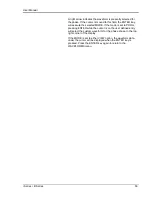
Voltage sensing for regulation and measurement can be
selected for internal or external. External voltage sensing can
compensate for voltage drops caused by load cable impedance.
To achieve the best output regulation select external sense and
connect the voltage sense wires at the load.
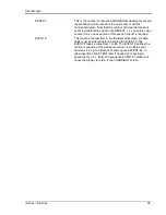
The number of outputs in a multibox system with the Mode-iX
option can be switched between one for 15000 VA single phase,
and three for 5000 VA per phase, three phase. If the Mode-iX
option is not installed, the number of outputs is fixed.
Summary of Contents for 10001i
Page 2: ......
Page 3: ......
Page 6: ...ii This page intentionally left blank...
Page 38: ...User Manual 24 i Series iX Series Figure 3 5 Rear Panel View for the 3001i 3001iX...
Page 39: ...User Manual i Series iX Series 25 Figure 3 6 Rear Panel View for the 5001i 5001iX...
Page 43: ...User Manual i Series iX Series 29 Figure 3 8 Functional Test Setup...
Page 44: ...User Manual 30 i Series iX Series Figure 3 9 Single Phase 10000 VA System 10001iX i...
Page 46: ...User Manual 32 i Series iX Series Figure 3 11 Single Phase 15000 VA System 15001iX i...
Page 48: ...User Manual 34 i Series iX Series Figure 3 13 Connection With MODE Option...
Page 118: ...User Manual 104 i Series iX Series Figure 5 2 Power Source Module Block Diagram...
Page 121: ...User Manual i Series iX Series 107 Figure 5 3 5001i Internal Layout...
Page 122: ...User Manual 108 i Series iX Series Figure 5 4 Logic Board LED s...
Page 124: ...User Manual 110 i Series iX Series Figure 5 5 AC Power Stage Layout...
Page 125: ...User Manual i Series iX Series 111 Figure 5 6 AC Control Logic Block Diagram...
Page 138: ...User Manual 124 i Series iX Series Figure 6 3 Adjustment Location...
Page 152: ...User Manual 138 i Series iX Series Figure 9 4 Voltage Modulation...
Page 219: ...User Manual i Series iX Series 205 Figure 9 36 Example Connection With 5001iX and EOS 1...
Page 221: ...User Manual i Series iX Series 207 Figure 9 38 15003iX CTS EOS3 LR3...
Page 222: ...User Manual 208 i Series iX Series Figure 9 39 15003iX 3 EOS3...
Page 233: ...User Manual i Series iX Series 219 Figure 9 41 Example Connection With MODE iX...
Page 240: ...User Manual 226 i Series iX Series Figure 9 42 Example Connections With OMNI 1 18i...
Page 241: ...User Manual i Series iX Series 227 Figure 9 43 Example Connections With OMNI 3 18i...

