


User Manual
i Series / iX Series
49
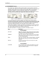
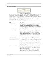
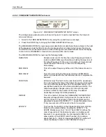
PEAK CURR
This readout reflects the peak current value detected at the
output. To measure inrush current for a unit under test, open the
output relay and reset the peak current value using the PEAK
CURR RESET entry. Then program the output voltage and
frequency and turn on the output relay. The peak current
measurement will continuously track the maximum current value
detected until reset.
POWER FACTOR
This readout shows the power factor of the load.
CREST FACTOR
This readout displays the ratio between peak current and rms
current.
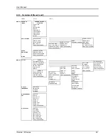
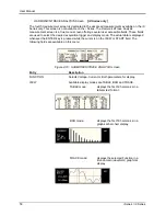
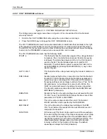
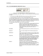
MEASUREMENT 3
[iX Series only]
VOLT THD
This readout displays the total voltage distortion for the selected
phase.
CURR THD
This readout displays the total current distortion for the selected
phase.
INST PK CURR
This readout reflects the instantaneous peak current value
detected at the output. This value is updated continuously and
does not require a reset operation like the PEAK CURR readout.
The instantaneous peak current does not use a track and hold
mechanism like the PEAK CURR measurement in the
MEASUREMENT 2 screen. Instead, it tracks the peak current
on a cycle by cycle basis. The INST PK CURR typically tracks
the rms current and the crest factor.
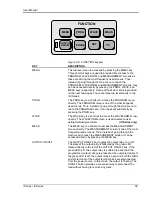
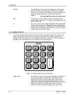
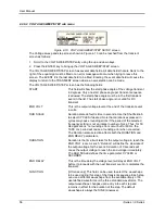
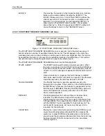
Update Program Functions from Measurement Screen
The Shuttle can be used to update program parameters such as voltage, frequency or current
from the measurement screen. This can be achieved with the following sequence:
1. Select the program 1 screen using the PROG key.
2. Use the up and down key to select the desired function to update. (Selects parameter that
will be changed by the shuttle once in the MEAS1 screen)
3. Select the measurement 1 screen by pressing the MEAS key.
4. The pointer symbol (
) points to the programmed parameter (V,F or CL) that will be
affected by turning the shuttle.
Summary of Contents for 10001i
Page 2: ......
Page 3: ......
Page 6: ...ii This page intentionally left blank...
Page 38: ...User Manual 24 i Series iX Series Figure 3 5 Rear Panel View for the 3001i 3001iX...
Page 39: ...User Manual i Series iX Series 25 Figure 3 6 Rear Panel View for the 5001i 5001iX...
Page 43: ...User Manual i Series iX Series 29 Figure 3 8 Functional Test Setup...
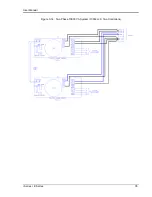
Page 44: ...User Manual 30 i Series iX Series Figure 3 9 Single Phase 10000 VA System 10001iX i...
Page 46: ...User Manual 32 i Series iX Series Figure 3 11 Single Phase 15000 VA System 15001iX i...
Page 48: ...User Manual 34 i Series iX Series Figure 3 13 Connection With MODE Option...
Page 118: ...User Manual 104 i Series iX Series Figure 5 2 Power Source Module Block Diagram...
Page 121: ...User Manual i Series iX Series 107 Figure 5 3 5001i Internal Layout...
Page 122: ...User Manual 108 i Series iX Series Figure 5 4 Logic Board LED s...
Page 124: ...User Manual 110 i Series iX Series Figure 5 5 AC Power Stage Layout...
Page 125: ...User Manual i Series iX Series 111 Figure 5 6 AC Control Logic Block Diagram...
Page 138: ...User Manual 124 i Series iX Series Figure 6 3 Adjustment Location...
Page 152: ...User Manual 138 i Series iX Series Figure 9 4 Voltage Modulation...
Page 219: ...User Manual i Series iX Series 205 Figure 9 36 Example Connection With 5001iX and EOS 1...
Page 221: ...User Manual i Series iX Series 207 Figure 9 38 15003iX CTS EOS3 LR3...
Page 222: ...User Manual 208 i Series iX Series Figure 9 39 15003iX 3 EOS3...
Page 233: ...User Manual i Series iX Series 219 Figure 9 41 Example Connection With MODE iX...
Page 240: ...User Manual 226 i Series iX Series Figure 9 42 Example Connections With OMNI 1 18i...
Page 241: ...User Manual i Series iX Series 227 Figure 9 43 Example Connections With OMNI 3 18i...