User Manual
i Series / iX Series
143
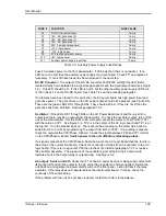
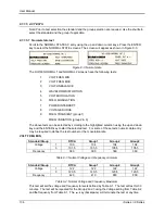
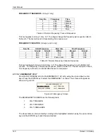
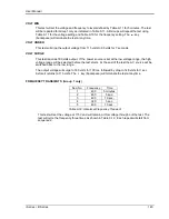
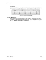
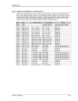
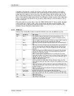
VOLT FREQ MIN
Standard/Group
RTCA
Group1
Group2
Group3
Voltage
1Ф
100
104
104
104
3Ф
101.5
105.5
105.5
105.5
Frequency
360
360
360
360
Table 9-7: Emergency Voltage and Frequency Minimum
Standard/Group
RTCA
Group1
Group2
Group3
Voltage
1Ф
122
122
122
122
3Ф
120.5
120.5
120.5
120.5
Frequency
440
440
650
800
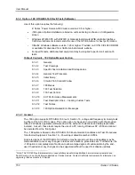
Table 9-8: Emergency Voltage and Frequency Maximum
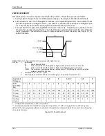
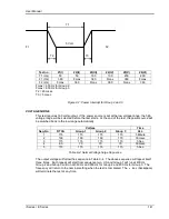
This test is test will set the voltage and frequency for a level defined by Table 9-7. The test will
last for 30 minutes. The test will be repeated using the voltage from Table 9-8 and frequency
from Table 9-7. The
key (backspace) will terminate the test at any time.
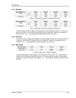
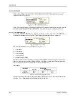
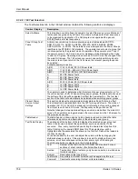
VOLT FREQ MAX
This test will set the voltage and frequency for a level defined by Table 9-8. The test will last for
30 minutes. The test will be repeated using the voltage from Table 9-7 and frequency from
Table 9-8. The
key (backspace) will terminate the test at any time.
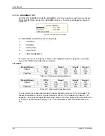
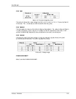
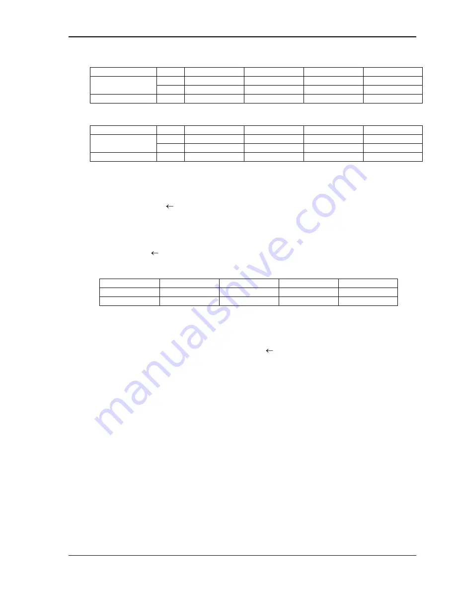
VOLT UNBALANCE
Standard/Group
RTCA
Group1
Group2
Group3
Voltage offset
8
8
8
12
Frequency
400
400
360/650
360/800
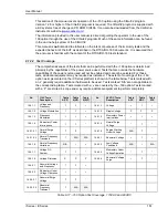
Table 9-9: Emergency Voltage Unbalance
This test will change the output voltage for each phase from 115 volts to 115V + offset. Refer to
Table 9-9 for the offset value and the Frequency. The test will last 30 minutes. The test will be
repeated for a second Frequency if applicable. The
key (backspace) will terminate the test at
any time.
Summary of Contents for 10001i
Page 2: ......
Page 3: ......
Page 6: ...ii This page intentionally left blank...
Page 38: ...User Manual 24 i Series iX Series Figure 3 5 Rear Panel View for the 3001i 3001iX...
Page 39: ...User Manual i Series iX Series 25 Figure 3 6 Rear Panel View for the 5001i 5001iX...
Page 43: ...User Manual i Series iX Series 29 Figure 3 8 Functional Test Setup...
Page 44: ...User Manual 30 i Series iX Series Figure 3 9 Single Phase 10000 VA System 10001iX i...
Page 46: ...User Manual 32 i Series iX Series Figure 3 11 Single Phase 15000 VA System 15001iX i...
Page 48: ...User Manual 34 i Series iX Series Figure 3 13 Connection With MODE Option...
Page 118: ...User Manual 104 i Series iX Series Figure 5 2 Power Source Module Block Diagram...
Page 121: ...User Manual i Series iX Series 107 Figure 5 3 5001i Internal Layout...
Page 122: ...User Manual 108 i Series iX Series Figure 5 4 Logic Board LED s...
Page 124: ...User Manual 110 i Series iX Series Figure 5 5 AC Power Stage Layout...
Page 125: ...User Manual i Series iX Series 111 Figure 5 6 AC Control Logic Block Diagram...
Page 138: ...User Manual 124 i Series iX Series Figure 6 3 Adjustment Location...
Page 152: ...User Manual 138 i Series iX Series Figure 9 4 Voltage Modulation...
Page 219: ...User Manual i Series iX Series 205 Figure 9 36 Example Connection With 5001iX and EOS 1...
Page 221: ...User Manual i Series iX Series 207 Figure 9 38 15003iX CTS EOS3 LR3...
Page 222: ...User Manual 208 i Series iX Series Figure 9 39 15003iX 3 EOS3...
Page 233: ...User Manual i Series iX Series 219 Figure 9 41 Example Connection With MODE iX...
Page 240: ...User Manual 226 i Series iX Series Figure 9 42 Example Connections With OMNI 1 18i...
Page 241: ...User Manual i Series iX Series 227 Figure 9 43 Example Connections With OMNI 3 18i...