


User Manual
156
i Series / iX Series
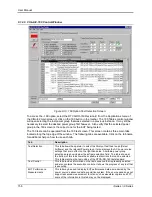
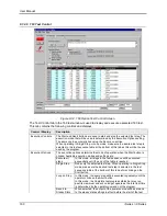
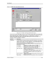
9.1.2.6 CIGui32 -160 Control Window
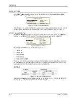
Figure 9-13: 160 Option Test Selection Screen.
To access the
–160 option, select the RTCA/DO-160 Revision E from the Applications menu of
the CIGui32 main screen or click on the 160 button in the toolbar. The 160 Tables control window
will open selecting the last power group that was selected in a previous instance. It may still be
necessary to select the desired power group first however. Also verify that the selected power
group in the 160 screen is the correct one for the EUT being tested.
The 160 tests can be operated from the 160 test screen. This screen contains three main tabs
located along the top edge of the window. The following tabs are available. Click on the tab name
for additional help on how to use each tab.
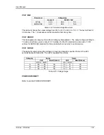
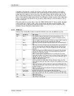
Tab
Description
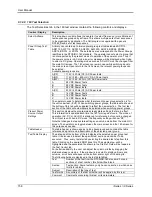
Test Selection
This tab allows the operator to select the library of test files to use (Select
Airframe) and the relevant Power group. It also displays the AC power source
settings that are in effect on the right hand side. Available power group
selections are shown below the airframe selection field. The table shown at
the bottom of this tab shows the available test sections that can be selected.
This table matches the test outline of the RTCA/DO-160 test standard.
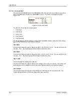
Test Control
This tab provides information on the test sequence that is presently selected
and also contains the execution controls. It shows the progress of any test that
is executing.
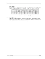
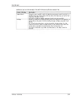
EUT Performance
Measurements
This tab may be used to display EUT performance data as measured by the
power source‟s advanced data acquisition system. If the source used does not
support advanced measurement function such as waveform capture and FFT,
some of the information in this tab may not be displayed.
Summary of Contents for 10001i
Page 2: ......
Page 3: ......
Page 6: ...ii This page intentionally left blank...
Page 38: ...User Manual 24 i Series iX Series Figure 3 5 Rear Panel View for the 3001i 3001iX...
Page 39: ...User Manual i Series iX Series 25 Figure 3 6 Rear Panel View for the 5001i 5001iX...
Page 43: ...User Manual i Series iX Series 29 Figure 3 8 Functional Test Setup...
Page 44: ...User Manual 30 i Series iX Series Figure 3 9 Single Phase 10000 VA System 10001iX i...
Page 46: ...User Manual 32 i Series iX Series Figure 3 11 Single Phase 15000 VA System 15001iX i...
Page 48: ...User Manual 34 i Series iX Series Figure 3 13 Connection With MODE Option...
Page 118: ...User Manual 104 i Series iX Series Figure 5 2 Power Source Module Block Diagram...
Page 121: ...User Manual i Series iX Series 107 Figure 5 3 5001i Internal Layout...
Page 122: ...User Manual 108 i Series iX Series Figure 5 4 Logic Board LED s...
Page 124: ...User Manual 110 i Series iX Series Figure 5 5 AC Power Stage Layout...
Page 125: ...User Manual i Series iX Series 111 Figure 5 6 AC Control Logic Block Diagram...
Page 138: ...User Manual 124 i Series iX Series Figure 6 3 Adjustment Location...
Page 152: ...User Manual 138 i Series iX Series Figure 9 4 Voltage Modulation...
Page 219: ...User Manual i Series iX Series 205 Figure 9 36 Example Connection With 5001iX and EOS 1...
Page 221: ...User Manual i Series iX Series 207 Figure 9 38 15003iX CTS EOS3 LR3...
Page 222: ...User Manual 208 i Series iX Series Figure 9 39 15003iX 3 EOS3...
Page 233: ...User Manual i Series iX Series 219 Figure 9 41 Example Connection With MODE iX...
Page 240: ...User Manual 226 i Series iX Series Figure 9 42 Example Connections With OMNI 1 18i...
Page 241: ...User Manual i Series iX Series 227 Figure 9 43 Example Connections With OMNI 3 18i...


