


User Manual
i Series / iX Series
51
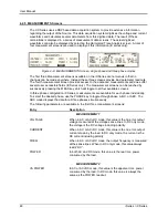
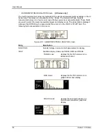
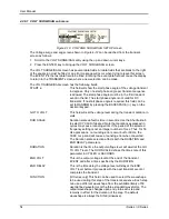
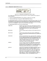
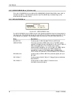
DATA MODE
Selects absolute or relative harmonics display for TABLE and
BAR view modes. In relative mode, all harmonics are shown in a
percentage of the fundamental which is normalized at 100 %. In
absolute mode, the harmonic amplitudes are shown in absolute
volts or amperes.
This mode does not apply to the TRACE view display mode and
is ignored when this mode is selected.
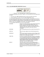
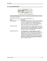
SCALE
Sets the horizontal time axis for the TRACE view display mode.
The field can range from 4 ms to 104 ms in single phase mode
or 12 ms to 312 ms in three phase mode.
This parameter is ignored when the TABLE or BAR view display
mode is selected.
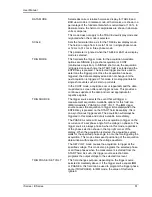
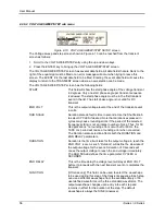
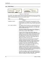
TRIG MODE
This field sets the trigger mode for the acquisition. Available
options are SINGLE (single shot acquisition) or CONT
(continuous acquisition). In SINGLE shot mode, the acquisition
is triggered once each time the START field is selected and the
ENTER key is pressed. The selected trigger source is used to
determine the trigger point. Once the acquisition has been
triggered, the data are displayed and do not change until the
next acquisition is triggered. This mode is most appropriate for
single shot events such as start up currents.
In the CONT mode, acquisitions occur repeatedly and the data
is updated on screen after each trigger occurs. This provides a
continuous update of the data and is most appropriate for
repetitive signals.
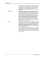
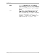
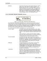
TRIG SOURCE
The trigger source selects the event that will trigger a
measurement acquisition. Available options for this field are
IMM (immediate), PHASE A or SET VOLT. The IMM trigger
source causes the acquisition to trigger immediately when the
ENTER key is pressed on the START field. Essentially, this is
an asynchronous trigger event. The acquisition will always be
triggered in this mode and data is available immediately.
The PHASE A source will cause the acquisition to trigger on the
occurrence of a set phase angle for the voltage on phase A. The
trigger source is always phase A when in this mode, regardless
of the phase selection shown in the top right corner of the
display. When the acquisition is started, the acquisition system
waits for the specified phase angle to occur before triggering the
acquisition. This mode allows exact positioning of the acquisition
data window with respect to the voltage waveform.
The SET VOLT mode causes the acquisition to trigger at the
specified voltage. This mode also programs the selected phase
or all three phases when the measurement is started from the
START field. As such, this trigger source selection also
programs the output voltage to the selected rms level.
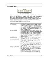
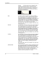
TRIG PHASE / SET VOLT
This field changes purpose, depending on the trigger source
selected immediately above it. If the trigger source equals IMM
or PHASE A, this field can be used to program the trigger phase
angle (TRIG PHASE). In IMM mode, the value of this field is
ignored.
Summary of Contents for 10001i
Page 2: ......
Page 3: ......
Page 6: ...ii This page intentionally left blank...
Page 38: ...User Manual 24 i Series iX Series Figure 3 5 Rear Panel View for the 3001i 3001iX...
Page 39: ...User Manual i Series iX Series 25 Figure 3 6 Rear Panel View for the 5001i 5001iX...
Page 43: ...User Manual i Series iX Series 29 Figure 3 8 Functional Test Setup...
Page 44: ...User Manual 30 i Series iX Series Figure 3 9 Single Phase 10000 VA System 10001iX i...
Page 46: ...User Manual 32 i Series iX Series Figure 3 11 Single Phase 15000 VA System 15001iX i...
Page 48: ...User Manual 34 i Series iX Series Figure 3 13 Connection With MODE Option...
Page 118: ...User Manual 104 i Series iX Series Figure 5 2 Power Source Module Block Diagram...
Page 121: ...User Manual i Series iX Series 107 Figure 5 3 5001i Internal Layout...
Page 122: ...User Manual 108 i Series iX Series Figure 5 4 Logic Board LED s...
Page 124: ...User Manual 110 i Series iX Series Figure 5 5 AC Power Stage Layout...
Page 125: ...User Manual i Series iX Series 111 Figure 5 6 AC Control Logic Block Diagram...
Page 138: ...User Manual 124 i Series iX Series Figure 6 3 Adjustment Location...
Page 152: ...User Manual 138 i Series iX Series Figure 9 4 Voltage Modulation...
Page 219: ...User Manual i Series iX Series 205 Figure 9 36 Example Connection With 5001iX and EOS 1...
Page 221: ...User Manual i Series iX Series 207 Figure 9 38 15003iX CTS EOS3 LR3...
Page 222: ...User Manual 208 i Series iX Series Figure 9 39 15003iX 3 EOS3...
Page 233: ...User Manual i Series iX Series 219 Figure 9 41 Example Connection With MODE iX...
Page 240: ...User Manual 226 i Series iX Series Figure 9 42 Example Connections With OMNI 1 18i...
Page 241: ...User Manual i Series iX Series 227 Figure 9 43 Example Connections With OMNI 3 18i...