


User Manual
274
i Series / iX Series
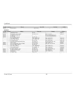
Test No. Section
Subject
Test Limits
Comment
File Ref.
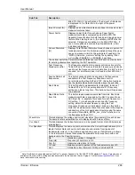
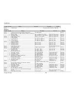
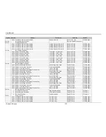
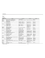
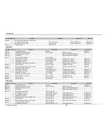
TVF301
Abnormal Steady State Limits for Voltage and Frequency
100V to 125V RMS, 360Hz to 800
Hz
Apply for 30 mins
FTVF301
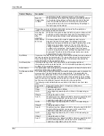
TVF302
Abnormal Voltage Transients
400-1 400 Hz, Overvoltage Transients
Peak Voltage 180V RMS
Table TVF302-2 A-G
FTVF302-400-1
400-2 400 Hz, Undervoltage Transients
Low Voltage 45V RMS
Table TVF302-2 H-N
FTVF302-400-2
400-3 400 Hz, Combined Transient
45V RMS to 180V RMS
Table TVF302-2 O
FTVF302-400-3
360-1 360 Hz, Overvoltage Transients
Peak Voltage 180V RMS
Table TVF302-2 A-G
FTVF302-360-1
360-2 360 Hz, Undervoltage Transients
Low Voltage 45V RMS
Table TVF302-2 H-N
FTVF302-360-2
360-3 360 Hz, Combined Transient
45V RMS to 180V RMS
Table TVF302-2 O
FTVF302-360-3
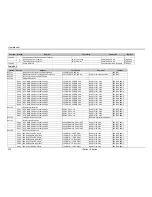
600-1 600 Hz, Overvoltage Transients
Peak Voltage 180V RMS
Table TVF302-2 A-G
FTVF302-600-1
600-2 600 Hz, Undervoltage Transients
Low Voltage 45V RMS
Table TVF302-2 H-N
FTVF302-600-2
600-3 600 Hz, Combined Transient
45V RMS to 180V RMS
Table TVF302-2 O
FTVF302-600-3
800-1 800 Hz, Overvoltage Transients
Peak Voltage 180V RMS
Table TVF302-2 A-G
FTVF302-800-1
800-2 800 Hz, Undervoltage Transients
Low Voltage 45V RMS
Table TVF302-2 H-N
FTVF302-800-2
800-3 800 Hz, Combined Transient
45V RMS to 180V RMS
Table TVF302-2 O
FTVF302-800-3
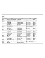
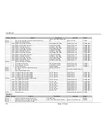
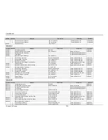
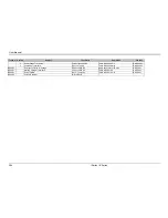
TVF303
Abnormal Frequency Transients
1
Overfrequency Transients
High Frequency 800 Hz
Table TVF303-2 A-D
FTVF303-1
2
Underfrequency Transients
Low Frequency 360 Hz
Table TVF303-2 E-H
FTVF303-2
3
Combined Transient
360 Hz to 800 Hz
Table TVF303-2 I
FTVF303-3
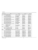
TVF401
Emergency Limits for Voltage and Frequency
Perform Test TVF102
TVF501
No Tests
N/A to AC Utilization Equipment
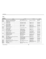
TVF601
Power Failure (Single Phase)
400-1 115V RMS, 400 Hz nominal settings
0V for 7 seconds
Table TVF601-2
FTVF601-400-1
360-1 115V RMS, 360 Hz nominal settings
0V for 7 seconds
Table TVF601-2
FTVF601-360-1
600-1 115V RMS, 600 Hz nominal settings
0V for 7 seconds
Table TVF601-2
FTVF601-600-1
800-1 115V RMS, 800 Hz nominal settings
0V for 7 seconds
Table TVF601-2
FTVF601-800-1
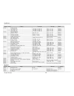
TVF602
One Phase and Two Phase Power Failures
400-1 One Phase Power Failures
0V for 7 seconds
Table TVF602-2 A-F
FTVF602-400-1
400-2 Two Phase Power Failures
0V for 30 mins
Table TVF602-2 G-J
FTVF602-400-2
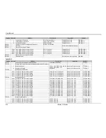
360-1 One Phase Power Failures
0V for 7 seconds
Table TVF602-2 A-F
FTVF602-360-1
360-2 Two Phase Power Failures
0V for 30 mins
Table TVF602-2 G-J
FTVF602-360-2
600-1 One Phase Power Failures
0V for 7 seconds
Table TVF602-2 A-F
FTVF602-600-1
600-2 Two Phase Power Failures
0V for 30 mins
Table TVF602-2 G-J
FTVF602-600-2
800-1 One Phase Power Failures
0V for 7 seconds
Table TVF602-2 A-F
FTVF602-800-1
800-2 Two Phase Power Failures
0V for 30 mins
Table TVF602-2 G-J
FTVF602-800-2
TVF603
Phase Reversal
Phase reversal done physically FTVF603
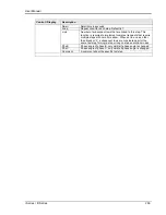
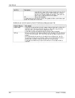
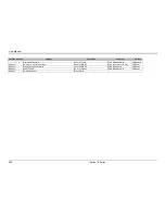
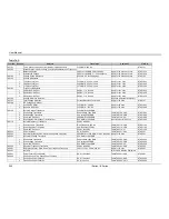
Table SXF:
Test No. Section
Subject
Test Limits
Comment
File Ref.
SXF101
Load and Current Harmonic Measurements
115V RMS, 60 Hz
FSXF101
SXF102
Steady State Limits for Voltage and Frequency
105V to 125V RMS, 59.75 to 60.25 Hz
Apply for 30 mins each test
FSXF102
SXF103
No Test, Done so test numbers coincide
Summary of Contents for 10001i
Page 2: ......
Page 3: ......
Page 6: ...ii This page intentionally left blank...
Page 38: ...User Manual 24 i Series iX Series Figure 3 5 Rear Panel View for the 3001i 3001iX...
Page 39: ...User Manual i Series iX Series 25 Figure 3 6 Rear Panel View for the 5001i 5001iX...
Page 43: ...User Manual i Series iX Series 29 Figure 3 8 Functional Test Setup...
Page 44: ...User Manual 30 i Series iX Series Figure 3 9 Single Phase 10000 VA System 10001iX i...
Page 46: ...User Manual 32 i Series iX Series Figure 3 11 Single Phase 15000 VA System 15001iX i...
Page 48: ...User Manual 34 i Series iX Series Figure 3 13 Connection With MODE Option...
Page 118: ...User Manual 104 i Series iX Series Figure 5 2 Power Source Module Block Diagram...
Page 121: ...User Manual i Series iX Series 107 Figure 5 3 5001i Internal Layout...
Page 122: ...User Manual 108 i Series iX Series Figure 5 4 Logic Board LED s...
Page 124: ...User Manual 110 i Series iX Series Figure 5 5 AC Power Stage Layout...
Page 125: ...User Manual i Series iX Series 111 Figure 5 6 AC Control Logic Block Diagram...
Page 138: ...User Manual 124 i Series iX Series Figure 6 3 Adjustment Location...
Page 152: ...User Manual 138 i Series iX Series Figure 9 4 Voltage Modulation...
Page 219: ...User Manual i Series iX Series 205 Figure 9 36 Example Connection With 5001iX and EOS 1...
Page 221: ...User Manual i Series iX Series 207 Figure 9 38 15003iX CTS EOS3 LR3...
Page 222: ...User Manual 208 i Series iX Series Figure 9 39 15003iX 3 EOS3...
Page 233: ...User Manual i Series iX Series 219 Figure 9 41 Example Connection With MODE iX...
Page 240: ...User Manual 226 i Series iX Series Figure 9 42 Example Connections With OMNI 1 18i...
Page 241: ...User Manual i Series iX Series 227 Figure 9 43 Example Connections With OMNI 3 18i...