


User Manual
46
i Series / iX Series
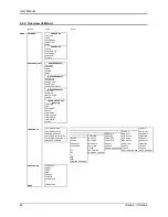
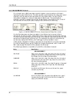
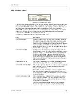
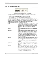
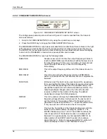
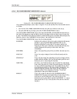
4.2.4 PROGRAM Menu
Figure 4-8: PROGRAM Menu
The PROGRAM menu is shown in Figure 4-8. It can be reached in one of two ways:
1. by selecting the PROGRAM entry in the MENU screen and pressing the ENTER key
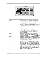
2. by pressing the PROG key in the FUNCTION keypad
The PROGRAM menu is used to change output parameters. The most commonly used
parameters are all located in PROGRAM 1. The PREVIOUS SCREEN entry, when selected, will
return the user to the most recently selected menu. This is normally the MENU screen unless the
PROGRAM menu was selected using the PROG key on the FUNCTION keypad. Less frequently
used parameters are located in PROGRAM 2 which can be reached from the PROGRAM 1
screen using the MORE selection, or by pressing the PROGRAM key twice.
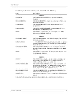
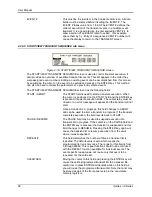
The following choices are available in the PROGRAM menus:
Entry
Description
PROGRAM 1
VOLTAGE
Programs the output voltage in rms. when in AC mode or
absolute voltage when in DC mode. In DC mode, negative
values can be entered.
FREQ
Programs the output frequency when in AC mode. If the unit is
in DC mode, the value for FREQ will be set to DC and cannot be
changed until AC mode is selected. When in AC mode, the
frequency can be changed from 16 Hz to 500 Hz. Values
entered that fall outside this range will generate a -200 RANGE
ERROR and will not be accepted.
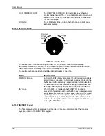
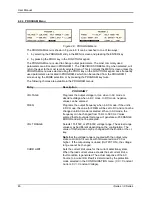
VOLT RANGE
Selects 135/150V or 270/300V voltage range. The actual range
values may be different depending on the configuration. The
value of this field can only be changed with the shuttle or the +/-
key.
Note
that the voltage range is coupled with the output relay
state on all i/iX AC sources with firmware revision 2.39 or
higher. If the output relay is closed (OUTPUT ON), the voltage
range cannot be changed.
CURR LIMIT
Sets the current limit value for the current detection system.
When the load current value exceeds the set current limit, a
fault condition is generated. The actual response of the AC
Source to a current limit fault is determined by the protection
mode selected in the CONFIGURATION menu. (CC = Constant
Current, CV = Constant Voltage).
Summary of Contents for 10001i
Page 2: ......
Page 3: ......
Page 6: ...ii This page intentionally left blank...
Page 38: ...User Manual 24 i Series iX Series Figure 3 5 Rear Panel View for the 3001i 3001iX...
Page 39: ...User Manual i Series iX Series 25 Figure 3 6 Rear Panel View for the 5001i 5001iX...
Page 43: ...User Manual i Series iX Series 29 Figure 3 8 Functional Test Setup...
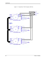
Page 44: ...User Manual 30 i Series iX Series Figure 3 9 Single Phase 10000 VA System 10001iX i...
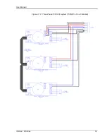
Page 46: ...User Manual 32 i Series iX Series Figure 3 11 Single Phase 15000 VA System 15001iX i...
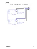
Page 48: ...User Manual 34 i Series iX Series Figure 3 13 Connection With MODE Option...
Page 118: ...User Manual 104 i Series iX Series Figure 5 2 Power Source Module Block Diagram...
Page 121: ...User Manual i Series iX Series 107 Figure 5 3 5001i Internal Layout...
Page 122: ...User Manual 108 i Series iX Series Figure 5 4 Logic Board LED s...
Page 124: ...User Manual 110 i Series iX Series Figure 5 5 AC Power Stage Layout...
Page 125: ...User Manual i Series iX Series 111 Figure 5 6 AC Control Logic Block Diagram...
Page 138: ...User Manual 124 i Series iX Series Figure 6 3 Adjustment Location...
Page 152: ...User Manual 138 i Series iX Series Figure 9 4 Voltage Modulation...
Page 219: ...User Manual i Series iX Series 205 Figure 9 36 Example Connection With 5001iX and EOS 1...
Page 221: ...User Manual i Series iX Series 207 Figure 9 38 15003iX CTS EOS3 LR3...
Page 222: ...User Manual 208 i Series iX Series Figure 9 39 15003iX 3 EOS3...
Page 233: ...User Manual i Series iX Series 219 Figure 9 41 Example Connection With MODE iX...
Page 240: ...User Manual 226 i Series iX Series Figure 9 42 Example Connections With OMNI 1 18i...
Page 241: ...User Manual i Series iX Series 227 Figure 9 43 Example Connections With OMNI 3 18i...


