User Manual
i Series / iX Series
37
4. Front Panel Operation
4.1 Tour of the Front Panel
The i and iX Series front panels are identical although some of the keys found on the front panel
are only used by iX Series models. If
your unit is an i Series, these keys will act as don‟t cares.
This chapter provides information on operating the i and iX Series AC sources from the front
panel keyboard.
Before operating the AC source using the front panel, it helps to understand the operation of the
front panel controls. Specifically, the operation of the knob, keyboard and the menu layout are
covered in the next few paragraphs.
4.1.1 Front Panel Controls and Indicators
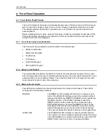
The front panel can be divided in a small number of functional areas:
Mains circuit breaker
Status Indicator lights
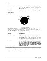
Shuttle knob
LCD display
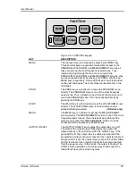
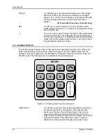
FUNCTION keypad
DATA ENTRY keypad
4.1.2 Mains Circuit Breaker
The circuit breaker located on the bottom left side of the front panel disconnects the AC source
from the three phase Line input. It will automatically trip when the input current rating of the unit is
exceeded due to some component failure. The contrasting black color and large size throw bar
make it easy to locate in case of an emergency.
4.1.3 Status Indicator Lights
Four LED status
indicators are located directly above the mains circuit breaker. These LED‟s
correspond to the following conditions:
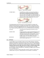
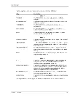
REMOTE
The REMOTE LED indicates that the unit is in remote control
mode. If the IEEE-488 interface is used, this indicator will be lit
whenever the REM line (REMOTE ENABLE) line is asserted by
the IEEE controller. If the RS232C interface is used, the
REMOTE state can be enabled by the controller using the
SYST:REM command. Any time the REMOTE LED is lit, the
front panel of the i Series unit is disabled. There is no LOCAL
button that allows the user to regain control of the front panel.
This prevents accidental change of settings in ATE applications.
OVERLOAD
The OVERLOAD LED indicates an output overload condition.
This condition can be controlled by setting the current limit value
in the PROGRAM menu. Removing the load using the OUTPUT
ON/OFF button will recover from an overload condition.
Summary of Contents for 10001i
Page 2: ......
Page 3: ......
Page 6: ...ii This page intentionally left blank...
Page 38: ...User Manual 24 i Series iX Series Figure 3 5 Rear Panel View for the 3001i 3001iX...
Page 39: ...User Manual i Series iX Series 25 Figure 3 6 Rear Panel View for the 5001i 5001iX...
Page 43: ...User Manual i Series iX Series 29 Figure 3 8 Functional Test Setup...
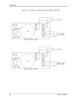
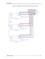
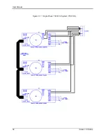
Page 44: ...User Manual 30 i Series iX Series Figure 3 9 Single Phase 10000 VA System 10001iX i...
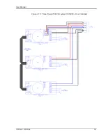
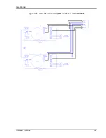
Page 46: ...User Manual 32 i Series iX Series Figure 3 11 Single Phase 15000 VA System 15001iX i...
Page 48: ...User Manual 34 i Series iX Series Figure 3 13 Connection With MODE Option...
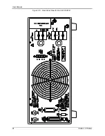
Page 118: ...User Manual 104 i Series iX Series Figure 5 2 Power Source Module Block Diagram...
Page 121: ...User Manual i Series iX Series 107 Figure 5 3 5001i Internal Layout...
Page 122: ...User Manual 108 i Series iX Series Figure 5 4 Logic Board LED s...
Page 124: ...User Manual 110 i Series iX Series Figure 5 5 AC Power Stage Layout...
Page 125: ...User Manual i Series iX Series 111 Figure 5 6 AC Control Logic Block Diagram...
Page 138: ...User Manual 124 i Series iX Series Figure 6 3 Adjustment Location...
Page 152: ...User Manual 138 i Series iX Series Figure 9 4 Voltage Modulation...
Page 219: ...User Manual i Series iX Series 205 Figure 9 36 Example Connection With 5001iX and EOS 1...
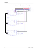
Page 221: ...User Manual i Series iX Series 207 Figure 9 38 15003iX CTS EOS3 LR3...
Page 222: ...User Manual 208 i Series iX Series Figure 9 39 15003iX 3 EOS3...
Page 233: ...User Manual i Series iX Series 219 Figure 9 41 Example Connection With MODE iX...
Page 240: ...User Manual 226 i Series iX Series Figure 9 42 Example Connections With OMNI 1 18i...
Page 241: ...User Manual i Series iX Series 227 Figure 9 43 Example Connections With OMNI 3 18i...

