User Manual
i Series / iX Series
105
5.4 Current Limit Board
The current limit board, A6, receives the oscillator signal and passes it through an amplifier
whose gain is controlled by a signal from the overcurrent circuit. The overcurrent circuit senses
the rms value of the current. If the load current exceeds the programmed value the output of this
sensing circuit reduces the output of the oscillator amplifier. The output of the unit then becomes
a constant current output, with the output voltage dropping as the load increases.
When two or three units are connected as a single phase system the MRA output from the
master oscillator amplifier drives all the power amplifiers over the system interface cable.
An overcurrent condition on any amplifier will act to reduce the output voltage and put the entire
system into the constant current mode.
5.5 Auxiliary Power Supply
The auxiliary power supply is mounted on the DC-DC power board. This assembly generates
nine low voltage outputs. These outputs from the auxiliary power supply provide logic power to
all the modules.
a) +/- 18V to the AC logic board and the oscillator.
b) +8V to the oscillator.
c) + 15V to the DC-DC converter.
d) Three + 18V supplies to the AC power amplifier gate drives.
e) +24V for the fan and relay power.
f) +8V for the digital front panel meter or GPIB/RS232 board.
All the supplies a), b) and e) have a common ground. The supplies in c) and d) are all isolated
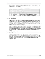
from each other and from a), b) and e). LED‟s on the AC logic board and the AC power board are
lit when each output is in regulation. If an overload condition causes the output to drop more
than 10% or the output has failed, the corresponding LED will extinguish. This feature is helpful
in troubleshooting the unit. See Service section 7.
Summary of Contents for 10001i
Page 2: ......
Page 3: ......
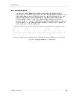
Page 6: ...ii This page intentionally left blank...
Page 38: ...User Manual 24 i Series iX Series Figure 3 5 Rear Panel View for the 3001i 3001iX...
Page 39: ...User Manual i Series iX Series 25 Figure 3 6 Rear Panel View for the 5001i 5001iX...
Page 43: ...User Manual i Series iX Series 29 Figure 3 8 Functional Test Setup...
Page 44: ...User Manual 30 i Series iX Series Figure 3 9 Single Phase 10000 VA System 10001iX i...
Page 46: ...User Manual 32 i Series iX Series Figure 3 11 Single Phase 15000 VA System 15001iX i...
Page 48: ...User Manual 34 i Series iX Series Figure 3 13 Connection With MODE Option...
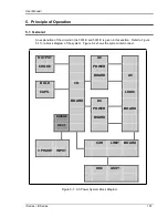
Page 118: ...User Manual 104 i Series iX Series Figure 5 2 Power Source Module Block Diagram...
Page 121: ...User Manual i Series iX Series 107 Figure 5 3 5001i Internal Layout...
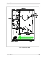
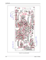
Page 122: ...User Manual 108 i Series iX Series Figure 5 4 Logic Board LED s...
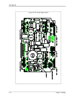
Page 124: ...User Manual 110 i Series iX Series Figure 5 5 AC Power Stage Layout...
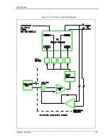
Page 125: ...User Manual i Series iX Series 111 Figure 5 6 AC Control Logic Block Diagram...
Page 138: ...User Manual 124 i Series iX Series Figure 6 3 Adjustment Location...
Page 152: ...User Manual 138 i Series iX Series Figure 9 4 Voltage Modulation...
Page 219: ...User Manual i Series iX Series 205 Figure 9 36 Example Connection With 5001iX and EOS 1...
Page 221: ...User Manual i Series iX Series 207 Figure 9 38 15003iX CTS EOS3 LR3...
Page 222: ...User Manual 208 i Series iX Series Figure 9 39 15003iX 3 EOS3...
Page 233: ...User Manual i Series iX Series 219 Figure 9 41 Example Connection With MODE iX...
Page 240: ...User Manual 226 i Series iX Series Figure 9 42 Example Connections With OMNI 1 18i...
Page 241: ...User Manual i Series iX Series 227 Figure 9 43 Example Connections With OMNI 3 18i...

