User Manual
42
i Series / iX Series
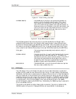
The cursor position can be moved by using the UP and DOWN keys located in the
DECIMAL
keypad.
Figure 4-6: Main Menu 1 screen
4.2 Menu Structure
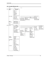
The next few pages show a map of the available menus in the i/iX Series. There are three main
level (level 1) menus from which all other menus can be reached. Frequently used (level 2)
menus have a short cut key that provides direct access. Examples of such menus are Program,
Measurements, and Waveform. In any case, there are never more than three levels of menus
although some menus may be spread across more than one screen.
4.2.1 MAIN Menus
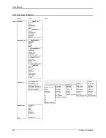
Figure 4-7: Menu 1 through 3
The top level menu is split in three parts, MENU 1 through MENU 3 to allow spacing between
menu entries. MENU 2 and 3 can be reached from MENU 1 by selecting the MORE entry or by
pressing the MENU key repeatedly, which will toggle from MENU 1 to 2 to 3 and back to 1. The
division of menu choices between the two screens is graphically illustrated in 4.2.2 by the boxes
in level 1. Each box represents one screen. Subsequent screens can be reached using the
MORE entry.
Summary of Contents for 10001i
Page 2: ......
Page 3: ......
Page 6: ...ii This page intentionally left blank...
Page 38: ...User Manual 24 i Series iX Series Figure 3 5 Rear Panel View for the 3001i 3001iX...
Page 39: ...User Manual i Series iX Series 25 Figure 3 6 Rear Panel View for the 5001i 5001iX...
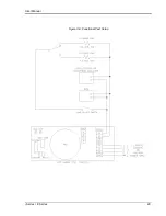
Page 43: ...User Manual i Series iX Series 29 Figure 3 8 Functional Test Setup...
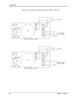
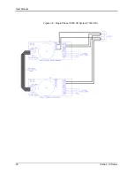
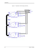
Page 44: ...User Manual 30 i Series iX Series Figure 3 9 Single Phase 10000 VA System 10001iX i...
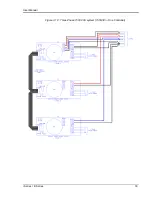
Page 46: ...User Manual 32 i Series iX Series Figure 3 11 Single Phase 15000 VA System 15001iX i...
Page 48: ...User Manual 34 i Series iX Series Figure 3 13 Connection With MODE Option...
Page 118: ...User Manual 104 i Series iX Series Figure 5 2 Power Source Module Block Diagram...
Page 121: ...User Manual i Series iX Series 107 Figure 5 3 5001i Internal Layout...
Page 122: ...User Manual 108 i Series iX Series Figure 5 4 Logic Board LED s...
Page 124: ...User Manual 110 i Series iX Series Figure 5 5 AC Power Stage Layout...
Page 125: ...User Manual i Series iX Series 111 Figure 5 6 AC Control Logic Block Diagram...
Page 138: ...User Manual 124 i Series iX Series Figure 6 3 Adjustment Location...
Page 152: ...User Manual 138 i Series iX Series Figure 9 4 Voltage Modulation...
Page 219: ...User Manual i Series iX Series 205 Figure 9 36 Example Connection With 5001iX and EOS 1...
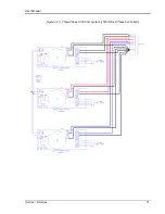
Page 221: ...User Manual i Series iX Series 207 Figure 9 38 15003iX CTS EOS3 LR3...
Page 222: ...User Manual 208 i Series iX Series Figure 9 39 15003iX 3 EOS3...
Page 233: ...User Manual i Series iX Series 219 Figure 9 41 Example Connection With MODE iX...
Page 240: ...User Manual 226 i Series iX Series Figure 9 42 Example Connections With OMNI 1 18i...
Page 241: ...User Manual i Series iX Series 227 Figure 9 43 Example Connections With OMNI 3 18i...

