User Manual
i Series / iX Series
243
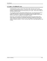
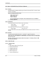
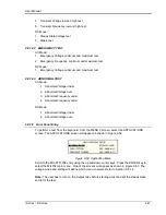
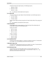
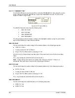
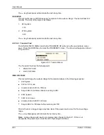
This test will change the output frequency in the following sequence:
393Hz for 1 minute.
407Hz for 1 minute.
400Hz for 1 minute.
The
key (backspace) will terminate the test at any time.
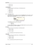
VOLT UNBALANCE
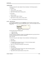
This test will change the output voltage for the selected phase only in the following sequence:
112V for 1 minute.
118V for 1 minute.
115V for 1 minute.
The test will be repeated on three phase systems to include all three phases if the coupling is set
to all.
The
key (backspace) will terminate the test at any time.
PHASE DIFFERENCE
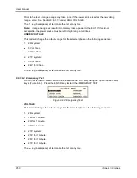
This test applies to three phase systems only. The phase angle for the selected phase will
change relative to phase A in the following sequence:
If phase B is selected:
236 for 1 minute.
244 for 1 minute.
240 for 1 minute.
If phase C is selected:
116 for 1 minute.
124 for 1 minute.
120 for 1 minute
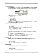
VOLTAGE MODULATION
This test will vary the output voltage by 2.5V rms over a period of one second. The test will last
for 2 minutes. The
key (backspace) will terminate the test at any time.
FREQUENCY MODULATION
This test will vary the output frequency by 4Hz over a period of one minute. The test will last for
4 minutes. The
key (backspace) will terminate the test at any time.
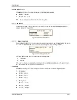
WAVEFORM DISTORTION
This test will generate a 5% THD voltage distortion on the output voltage waveform. The
distortion is caused by using a clipped sinewave. The test will last for 1 minute. The
key
(backspace) will terminate the test at any time.
Summary of Contents for 10001i
Page 2: ......
Page 3: ......
Page 6: ...ii This page intentionally left blank...
Page 38: ...User Manual 24 i Series iX Series Figure 3 5 Rear Panel View for the 3001i 3001iX...
Page 39: ...User Manual i Series iX Series 25 Figure 3 6 Rear Panel View for the 5001i 5001iX...
Page 43: ...User Manual i Series iX Series 29 Figure 3 8 Functional Test Setup...
Page 44: ...User Manual 30 i Series iX Series Figure 3 9 Single Phase 10000 VA System 10001iX i...
Page 46: ...User Manual 32 i Series iX Series Figure 3 11 Single Phase 15000 VA System 15001iX i...
Page 48: ...User Manual 34 i Series iX Series Figure 3 13 Connection With MODE Option...
Page 118: ...User Manual 104 i Series iX Series Figure 5 2 Power Source Module Block Diagram...
Page 121: ...User Manual i Series iX Series 107 Figure 5 3 5001i Internal Layout...
Page 122: ...User Manual 108 i Series iX Series Figure 5 4 Logic Board LED s...
Page 124: ...User Manual 110 i Series iX Series Figure 5 5 AC Power Stage Layout...
Page 125: ...User Manual i Series iX Series 111 Figure 5 6 AC Control Logic Block Diagram...
Page 138: ...User Manual 124 i Series iX Series Figure 6 3 Adjustment Location...
Page 152: ...User Manual 138 i Series iX Series Figure 9 4 Voltage Modulation...
Page 219: ...User Manual i Series iX Series 205 Figure 9 36 Example Connection With 5001iX and EOS 1...
Page 221: ...User Manual i Series iX Series 207 Figure 9 38 15003iX CTS EOS3 LR3...
Page 222: ...User Manual 208 i Series iX Series Figure 9 39 15003iX 3 EOS3...
Page 233: ...User Manual i Series iX Series 219 Figure 9 41 Example Connection With MODE iX...
Page 240: ...User Manual 226 i Series iX Series Figure 9 42 Example Connections With OMNI 1 18i...
Page 241: ...User Manual i Series iX Series 227 Figure 9 43 Example Connections With OMNI 3 18i...


