


User Manual
186
i Series / iX Series
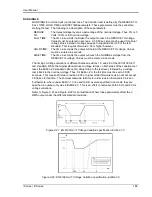
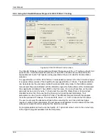
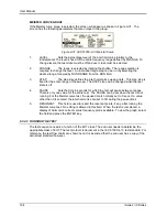
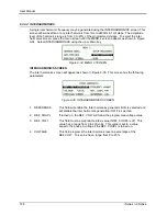
9.2.6 Using the CIGui32 Windows Program for IEC 61000-4-11 Testing
Figure 9-23: IEC 61000-4-11 GUI screen.
The CIGui32 Windows control program will detect the presence of the
–411 option on the iX/i AC
power source. It will also detect the presence of an EOS1 or EOS3 and use the EOS for the
appropriate test levels. Test reports can be generated at the end of a test for documentation
purposes.
To support Edition 2.0 of the IEC 61000-4-11 test standard, version 1.20 of the CIGui32 or higher
is required. Older versions of the Cigui32 will only support Edition 1.0 tests. The desired Edition
can be selected by the user and provides the relevant data entry mode for the Edition selected.
Generic tests files are distributed with the CIGui32 program for both editions of the test standard.
Files applicable to Edition 2.0 have ED20 in their file name. Do not mix these files, as the data
setup will not be correct if you do. To load a test file, select the Mode (Dips or Vars) and test
standard revision first, then use the File, Open menu to load the test parameters. Test
parameters can be a function of the EUT class. The different files provided with the program
cover the various EUT classes. The relevant EUT class 1, 2, 3 or X is listed in the file names.
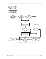
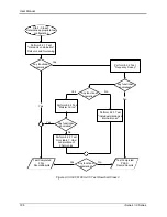
The user must select the desired test type before executing the test. Since both test types
require a number of test parameters, the test sequence parameters must be entered in the data
entry grid or loaded from disk using the File, Open menu entry.
For complete details on how to use the Cgui32
–411 option test screen, refer to the on-line help
of the Cigui32 program available from the Help menu.
Summary of Contents for 10001i
Page 2: ......
Page 3: ......
Page 6: ...ii This page intentionally left blank...
Page 38: ...User Manual 24 i Series iX Series Figure 3 5 Rear Panel View for the 3001i 3001iX...
Page 39: ...User Manual i Series iX Series 25 Figure 3 6 Rear Panel View for the 5001i 5001iX...
Page 43: ...User Manual i Series iX Series 29 Figure 3 8 Functional Test Setup...
Page 44: ...User Manual 30 i Series iX Series Figure 3 9 Single Phase 10000 VA System 10001iX i...
Page 46: ...User Manual 32 i Series iX Series Figure 3 11 Single Phase 15000 VA System 15001iX i...
Page 48: ...User Manual 34 i Series iX Series Figure 3 13 Connection With MODE Option...
Page 118: ...User Manual 104 i Series iX Series Figure 5 2 Power Source Module Block Diagram...
Page 121: ...User Manual i Series iX Series 107 Figure 5 3 5001i Internal Layout...
Page 122: ...User Manual 108 i Series iX Series Figure 5 4 Logic Board LED s...
Page 124: ...User Manual 110 i Series iX Series Figure 5 5 AC Power Stage Layout...
Page 125: ...User Manual i Series iX Series 111 Figure 5 6 AC Control Logic Block Diagram...
Page 138: ...User Manual 124 i Series iX Series Figure 6 3 Adjustment Location...
Page 152: ...User Manual 138 i Series iX Series Figure 9 4 Voltage Modulation...
Page 219: ...User Manual i Series iX Series 205 Figure 9 36 Example Connection With 5001iX and EOS 1...
Page 221: ...User Manual i Series iX Series 207 Figure 9 38 15003iX CTS EOS3 LR3...
Page 222: ...User Manual 208 i Series iX Series Figure 9 39 15003iX 3 EOS3...
Page 233: ...User Manual i Series iX Series 219 Figure 9 41 Example Connection With MODE iX...
Page 240: ...User Manual 226 i Series iX Series Figure 9 42 Example Connections With OMNI 1 18i...
Page 241: ...User Manual i Series iX Series 227 Figure 9 43 Example Connections With OMNI 3 18i...