User Manual
i Series / iX Series
133
9. Options
9.1 RTCA/DO-160 Option
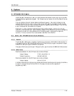
The RTCA/DO-160 Option is made up of both firmware that resides in the power source and the
CIGui32 Windows application program. The firmware covers revision D, and the CIGui32 covers
revision E.
The user interface for each implementation is different however. The revision D tests can be
operated directly from the power source‟s front panel or through the supplied CIGui32 program.
The Revision E tests can only be operated through the Cigui32 windows software. Thus, for Rev
E use, a Windows PC and interface is required.
Section 9.1.1 covers operation of the firmware based revision D tests. Section 9.1.2 covers
operation of the revision E test. Note that future updates of the CIGui32 may include overlapping
coverage for revision D in the software as the CIGui32 program is designed to support all
revisions. For now, revision D has no associated data files in the CIGui32.
9.1.1 Option
–160: RTCA/DO160 rev D Tests (Firmware)
9.1.1.1 General
The RTCA/DO-160D option is capable of performing all sections of RTCA/DO-160D, Section 16
and EUROCAE-14D / RTCA DO160D, Section 16 for the AC Source signal. A selection is made
available to specify the type of standard, and groups.
Throughout this document, Groups 1 through 3 will be used to refer to EUROCAE-14D standard.
9.1.1.2 Initial Setup
Nominal parameters for the AC Power source are as follows:
Output Voltage
115V L-N or 230V L-N
Output Frequency
360 Hz to 800 Hz
Nominal parameters for the DC Power source are as follows:
Output Voltage
28V or 14V L-N
A setting outside these nominal values will disable the test and will prevent accessing to its Menu
screens. To access the test for the 230V L-N, the power source must be capable of
programming 360V.
Summary of Contents for 10001i
Page 2: ......
Page 3: ......
Page 6: ...ii This page intentionally left blank...
Page 38: ...User Manual 24 i Series iX Series Figure 3 5 Rear Panel View for the 3001i 3001iX...
Page 39: ...User Manual i Series iX Series 25 Figure 3 6 Rear Panel View for the 5001i 5001iX...
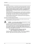
Page 43: ...User Manual i Series iX Series 29 Figure 3 8 Functional Test Setup...
Page 44: ...User Manual 30 i Series iX Series Figure 3 9 Single Phase 10000 VA System 10001iX i...
Page 46: ...User Manual 32 i Series iX Series Figure 3 11 Single Phase 15000 VA System 15001iX i...
Page 48: ...User Manual 34 i Series iX Series Figure 3 13 Connection With MODE Option...
Page 118: ...User Manual 104 i Series iX Series Figure 5 2 Power Source Module Block Diagram...
Page 121: ...User Manual i Series iX Series 107 Figure 5 3 5001i Internal Layout...
Page 122: ...User Manual 108 i Series iX Series Figure 5 4 Logic Board LED s...
Page 124: ...User Manual 110 i Series iX Series Figure 5 5 AC Power Stage Layout...
Page 125: ...User Manual i Series iX Series 111 Figure 5 6 AC Control Logic Block Diagram...
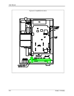
Page 138: ...User Manual 124 i Series iX Series Figure 6 3 Adjustment Location...
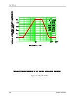
Page 152: ...User Manual 138 i Series iX Series Figure 9 4 Voltage Modulation...
Page 219: ...User Manual i Series iX Series 205 Figure 9 36 Example Connection With 5001iX and EOS 1...
Page 221: ...User Manual i Series iX Series 207 Figure 9 38 15003iX CTS EOS3 LR3...
Page 222: ...User Manual 208 i Series iX Series Figure 9 39 15003iX 3 EOS3...
Page 233: ...User Manual i Series iX Series 219 Figure 9 41 Example Connection With MODE iX...
Page 240: ...User Manual 226 i Series iX Series Figure 9 42 Example Connections With OMNI 1 18i...
Page 241: ...User Manual i Series iX Series 227 Figure 9 43 Example Connections With OMNI 3 18i...

