


User Manual
i Series / iX Series
113
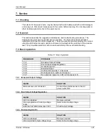
6. Calibration
The Routine Calibration should be performed every 12 months. Non-routine Calibration is only
required if a related assembly is replaced or if the periodic calibration is unsuccessful.
All standard models and configurations of the iX/i Series may be calibrated using a PC running
Windows 98/2000/XP, and the latest version of the CIGUI32 AC source control software. Refer
to the CIGUI32 online help file of the CIGUI32 software for additional procedures and guidance.
To download the latest version of the CIGUI32, visit
www.calinst.com
.
6.1 Calibration Equipment
Digital Phase Meter:
Krohn-Hite, Model 6620 or equivalent. (0.01° resolution, 0.02°
accuracy.)
Digital Multimeter:
Fluke 8506A
HP 34401A (two required)
10 milliohm Current Shunt:
Isotek Model RUG-Z-R010-0.1 or equivalent
1 milliohm Current Shunt:
Isotek Model RUG-Z-R001-0.1
(10001i/iX, 15001i/ix and
15003iX-MODE):
Load Bank:
Various high power load resistors will be needed.
Computer (Optional)
PC to operate California Instruments CIGui32.
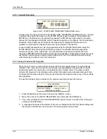
6.2 The Output Calibration Screen
To show the OUTPUT CALIBRATION screen for the first time press the MENU key twice to
display the MENU 3 screen. Press the or key several times to highlight OUTPUT CAL.
Press the ENTER key. Type 5000 and press the ENTER key to show the OUTPUT
CALIBRATION screen. Press the PHASE key to select the phase to be calibrated for a 15003iX
power system with one controller.
6.3 The Measurement Calibration Screen
To show the MEASUREMENT CALIBRATION screen follow the steps in paragraph 6.2. Select
the MEASUREMENT CAL function instead of OUTPUT CAL from the MENU 2 screen. If
another CALIBRATION screen has been accessed since power-up no password is needed. If a
password is needed use the value 5000.
Summary of Contents for 10001i
Page 2: ......
Page 3: ......
Page 6: ...ii This page intentionally left blank...
Page 38: ...User Manual 24 i Series iX Series Figure 3 5 Rear Panel View for the 3001i 3001iX...
Page 39: ...User Manual i Series iX Series 25 Figure 3 6 Rear Panel View for the 5001i 5001iX...
Page 43: ...User Manual i Series iX Series 29 Figure 3 8 Functional Test Setup...
Page 44: ...User Manual 30 i Series iX Series Figure 3 9 Single Phase 10000 VA System 10001iX i...
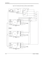
Page 46: ...User Manual 32 i Series iX Series Figure 3 11 Single Phase 15000 VA System 15001iX i...
Page 48: ...User Manual 34 i Series iX Series Figure 3 13 Connection With MODE Option...
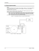
Page 118: ...User Manual 104 i Series iX Series Figure 5 2 Power Source Module Block Diagram...
Page 121: ...User Manual i Series iX Series 107 Figure 5 3 5001i Internal Layout...
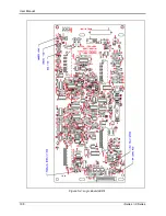
Page 122: ...User Manual 108 i Series iX Series Figure 5 4 Logic Board LED s...
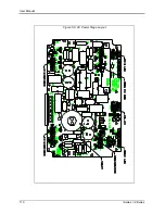
Page 124: ...User Manual 110 i Series iX Series Figure 5 5 AC Power Stage Layout...
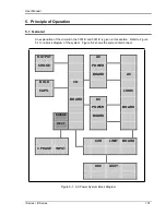
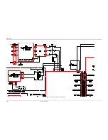
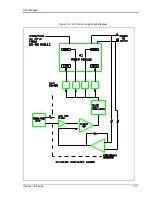
Page 125: ...User Manual i Series iX Series 111 Figure 5 6 AC Control Logic Block Diagram...
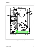
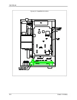
Page 138: ...User Manual 124 i Series iX Series Figure 6 3 Adjustment Location...
Page 152: ...User Manual 138 i Series iX Series Figure 9 4 Voltage Modulation...
Page 219: ...User Manual i Series iX Series 205 Figure 9 36 Example Connection With 5001iX and EOS 1...
Page 221: ...User Manual i Series iX Series 207 Figure 9 38 15003iX CTS EOS3 LR3...
Page 222: ...User Manual 208 i Series iX Series Figure 9 39 15003iX 3 EOS3...
Page 233: ...User Manual i Series iX Series 219 Figure 9 41 Example Connection With MODE iX...
Page 240: ...User Manual 226 i Series iX Series Figure 9 42 Example Connections With OMNI 1 18i...
Page 241: ...User Manual i Series iX Series 227 Figure 9 43 Example Connections With OMNI 3 18i...


