User Manual
i Series / iX Series
13
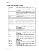
2.6 Special Features, Options and Accessories
Programmable
Impedance.
Output impedance programming available on models 3001iX,
5001iX, 9003iX and 15003iX only.
Parallel Operation:
Up to three units can be paralleled in a single-phase configuration
(with one master controller and one or two slave units). (10001iX
and 15001iX).
Three Phase Output:
Three units (all with single-phase controllers) can be connected in
a three-phase configuration using CLOCK and LOCK connections.
Requires
–LKM option in master and –LKS option in auxiliary
units. Recommended is use of 9003iX, 15003iX or 30003iX three
phase system however.
Rack Mount/Handles
Version:
Available rack mounting kit with slides and handles. Handles also
available as a separate option.
Controller:
Programmable controller front panel assembly.
Output Relay:
Standard output relay feature to isolate AC source from the load.
Output On/Off:
The output relay can be used to quickly disconnect the load. A
green status indicator displays the status of the output relay.
Three-Phase Output
9003iX/15003Ix
Three power sources with one controller in the Phase A power
source. The one controller controls all three outputs.
15003iX
– LKM/-LKS
Three power sources each with a controller for 3-phase output
- 704
Mil Std 704D & E test firmware.
Mil Std 704A, B, C, & F test software.
Note: Requires use of CIGui32 Windows application software provided
on CD ROM CIC496.
- 160
RTCA/DO-160C test firmware
- 411
IEC 1000-4-11 test firmware
- 413
IEC 1000-4-13 test firmware
-ABD
Airbus ABD0100.1.8 Test firmware.
Note: Requires use ofCIGui32 Windows application software provided on
CD ROM CIC496.
- LNS
Line sync option to synchronize output frequency to input mains
line frequency
-MODE-iX
Available for 9003iX and 15003iX configurations only. Switches
output configurations between single-phase and three-phase
mode of operation. Note that programmable impedance function
on systems with
–MODE-iX option is only available when in 3
phase mode.
- RMS
Rack mount slides
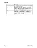
-OMNI-1-18i
Single phase lumped reference impedance network of IEC1000-3-
3 Flicker test
-OMNI-1-37i
Single phase lumped reference impedance network of IEC1000-3-
3 Flicker test
– High current.
-OMNI-3-18i
Three phase lumped reference impedance network of IEC1000-3-
Summary of Contents for 10001i
Page 2: ......
Page 3: ......
Page 6: ...ii This page intentionally left blank...
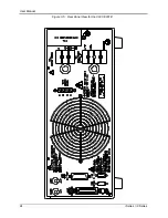
Page 38: ...User Manual 24 i Series iX Series Figure 3 5 Rear Panel View for the 3001i 3001iX...
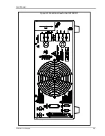
Page 39: ...User Manual i Series iX Series 25 Figure 3 6 Rear Panel View for the 5001i 5001iX...
Page 43: ...User Manual i Series iX Series 29 Figure 3 8 Functional Test Setup...
Page 44: ...User Manual 30 i Series iX Series Figure 3 9 Single Phase 10000 VA System 10001iX i...
Page 46: ...User Manual 32 i Series iX Series Figure 3 11 Single Phase 15000 VA System 15001iX i...
Page 48: ...User Manual 34 i Series iX Series Figure 3 13 Connection With MODE Option...
Page 118: ...User Manual 104 i Series iX Series Figure 5 2 Power Source Module Block Diagram...
Page 121: ...User Manual i Series iX Series 107 Figure 5 3 5001i Internal Layout...
Page 122: ...User Manual 108 i Series iX Series Figure 5 4 Logic Board LED s...
Page 124: ...User Manual 110 i Series iX Series Figure 5 5 AC Power Stage Layout...
Page 125: ...User Manual i Series iX Series 111 Figure 5 6 AC Control Logic Block Diagram...
Page 138: ...User Manual 124 i Series iX Series Figure 6 3 Adjustment Location...
Page 152: ...User Manual 138 i Series iX Series Figure 9 4 Voltage Modulation...
Page 219: ...User Manual i Series iX Series 205 Figure 9 36 Example Connection With 5001iX and EOS 1...
Page 221: ...User Manual i Series iX Series 207 Figure 9 38 15003iX CTS EOS3 LR3...
Page 222: ...User Manual 208 i Series iX Series Figure 9 39 15003iX 3 EOS3...
Page 233: ...User Manual i Series iX Series 219 Figure 9 41 Example Connection With MODE iX...
Page 240: ...User Manual 226 i Series iX Series Figure 9 42 Example Connections With OMNI 1 18i...
Page 241: ...User Manual i Series iX Series 227 Figure 9 43 Example Connections With OMNI 3 18i...

