User Manual
i Series / iX Series
319
9.10.4 Remote PROGRAMMING
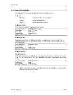
The following SCPI command will be used to control the WHM functions:
WHMeter:
[STATe]
Turn on or of the watt hour function
ETIMe?
Return the elapse time
WHOur?
Return the watt-hour in KWH
WHMeter[:STATe]
This command will start or stop the watt-hour function.
Command Syntax
WHMeter[:STATe]<bool>
Parameters
0 | OFF | 1 | ON
Examples
WHM ON
Query Syntax
WHM[:STATe]?
Returned Parameters
0 | 1
WHMeter:ETIMe?
This command will return the total amount of time the watt-hour meter accumulated. The
returned data has four fields separated by commas. These fields are hours, minutes, seconds
and milliseconds.
Command Syntax
WHMeter:ETIMe?
Parameters
none
Query Syntax
WHM:ETIM?
Returned Parameters
h,mm,ss,ms
WHMeter:WHOur?
Phase Selectable
This command will return the total accumulated kilowatt-hour for the selected phase. If coupling
is set to all, the value returned is the sum of all phases in the system irregardless of the selected
phase.
Command Syntax
WHMeter:WHOur?
Parameters
none
Query Syntax
WHM:WHO?
Returned Parameters
<numeric value>
Note
: If the watt-hour meter is active, the total power of all phases in the system will be
returned when querying the power.
Summary of Contents for 10001i
Page 2: ......
Page 3: ......
Page 6: ...ii This page intentionally left blank...
Page 38: ...User Manual 24 i Series iX Series Figure 3 5 Rear Panel View for the 3001i 3001iX...
Page 39: ...User Manual i Series iX Series 25 Figure 3 6 Rear Panel View for the 5001i 5001iX...
Page 43: ...User Manual i Series iX Series 29 Figure 3 8 Functional Test Setup...
Page 44: ...User Manual 30 i Series iX Series Figure 3 9 Single Phase 10000 VA System 10001iX i...
Page 46: ...User Manual 32 i Series iX Series Figure 3 11 Single Phase 15000 VA System 15001iX i...
Page 48: ...User Manual 34 i Series iX Series Figure 3 13 Connection With MODE Option...
Page 118: ...User Manual 104 i Series iX Series Figure 5 2 Power Source Module Block Diagram...
Page 121: ...User Manual i Series iX Series 107 Figure 5 3 5001i Internal Layout...
Page 122: ...User Manual 108 i Series iX Series Figure 5 4 Logic Board LED s...
Page 124: ...User Manual 110 i Series iX Series Figure 5 5 AC Power Stage Layout...
Page 125: ...User Manual i Series iX Series 111 Figure 5 6 AC Control Logic Block Diagram...
Page 138: ...User Manual 124 i Series iX Series Figure 6 3 Adjustment Location...
Page 152: ...User Manual 138 i Series iX Series Figure 9 4 Voltage Modulation...
Page 219: ...User Manual i Series iX Series 205 Figure 9 36 Example Connection With 5001iX and EOS 1...
Page 221: ...User Manual i Series iX Series 207 Figure 9 38 15003iX CTS EOS3 LR3...
Page 222: ...User Manual 208 i Series iX Series Figure 9 39 15003iX 3 EOS3...
Page 233: ...User Manual i Series iX Series 219 Figure 9 41 Example Connection With MODE iX...
Page 240: ...User Manual 226 i Series iX Series Figure 9 42 Example Connections With OMNI 1 18i...
Page 241: ...User Manual i Series iX Series 227 Figure 9 43 Example Connections With OMNI 3 18i...

